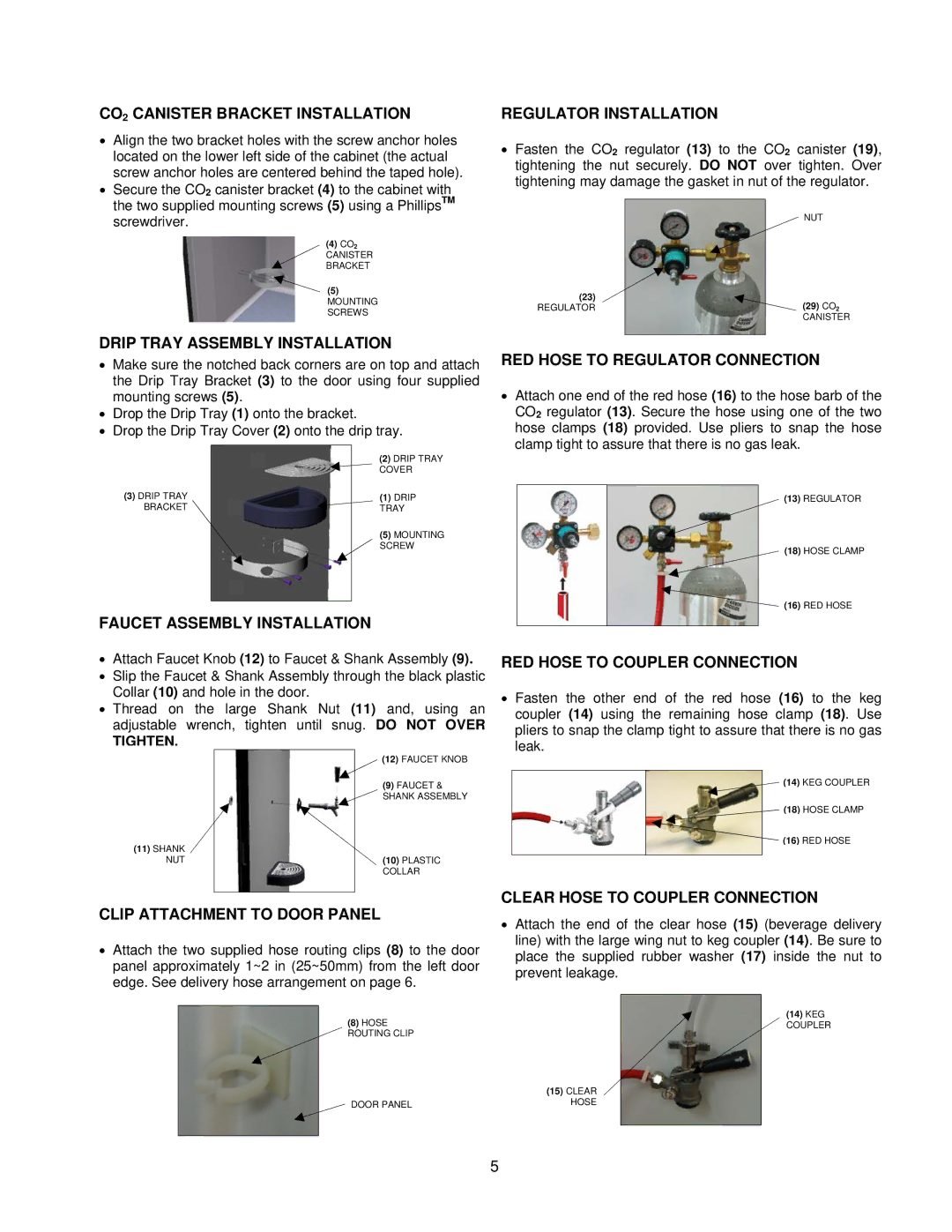
CO2 CANISTER BRACKET INSTALLATION
•Align the two bracket holes with the screw anchor holes located on the lower left side of the cabinet (the actual screw anchor holes are centered behind the taped hole).
•Secure the CO2 canister bracket (4) to the cabinet with the two supplied mounting screws (5) using a PhillipsTM screwdriver.
(4)CO2
CANISTER
BRACKET
(5) MOUNTING SCREWS
DRIP TRAY ASSEMBLY INSTALLATION
•Make sure the notched back corners are on top and attach the Drip Tray Bracket (3) to the door using four supplied mounting screws (5).
•Drop the Drip Tray (1) onto the bracket.
•Drop the Drip Tray Cover (2) onto the drip tray.
(2)DRIP TRAY
![]() COVER
COVER
(3) DRIP TRAY |
| (1) | DRIP |
BRACKET |
| TRAY | |
| (5) | MOUNTING | |
|
| SCREW | |
|
|
|
|
|
|
|
|
FAUCET ASSEMBLY INSTALLATION
•Attach Faucet Knob (12) to Faucet & Shank Assembly (9).
•Slip the Faucet & Shank Assembly through the black plastic Collar (10) and hole in the door.
•Thread on the large Shank Nut (11) and, using an adjustable wrench, tighten until snug. DO NOT OVER
REGULATOR INSTALLATION
•Fasten the CO2 regulator (13) to the CO2 canister (19), tightening the nut securely. DO NOT over tighten. Over tightening may damage the gasket in nut of the regulator.
NUT
(23)
REGULATOR | (29) CO2 |
CANISTER
RED HOSE TO REGULATOR CONNECTION
•Attach one end of the red hose (16) to the hose barb of the CO2 regulator (13). Secure the hose using one of the two hose clamps (18) provided. Use pliers to snap the hose clamp tight to assure that there is no gas leak.
(13)REGULATOR
(18)HOSE CLAMP
![]() (16) RED HOSE
(16) RED HOSE
RED HOSE TO COUPLER CONNECTION
• Fasten the other end of the red hose (16) to the keg |
coupler (14) using the remaining hose clamp (18). Use |
pliers to snap the clamp tight to assure that there is no gas |
TIGHTEN.
(11)SHANK NUT
(12) FAUCET KNOB
(9)FAUCET &
![]() SHANK ASSEMBLY
SHANK ASSEMBLY
(10)PLASTIC COLLAR
leak. |
(14) KEG COUPLER |
(18) HOSE CLAMP |
(16) RED HOSE |
CLEAR HOSE TO COUPLER CONNECTION
CLIP ATTACHMENT TO DOOR PANEL
•Attach the two supplied hose routing clips (8) to the door panel approximately 1~2 in (25~50mm) from the left door edge. See delivery hose arrangement on page 6.
(8)HOSE
ROUTING CLIP
DOOR PANEL
•Attach the end of the clear hose (15) (beverage delivery line) with the large wing nut to keg coupler (14). Be sure to place the supplied rubber washer (17) inside the nut to prevent leakage.
(14)KEG
COUPLER
(15)CLEAR HOSE
5