TOOLS AND
MATERIALS REQUIRED
TOOLS
❏Drill, electric or ratchet drive
❏
❏Common head and phillips head screwdriver
❏Pliers
❏Tape measure or ruler and pencil
 For Ducted Installations ONLY:
❏Saber saw or drywall saw
❏Metal snips
MATERIALS
❏Electrical wiring and supplies of type to comply with local codes
![]() ❏ Roof or wall cap
❏ Roof or wall cap ![]()
![]()
![]()
![]()
![]()
![]()
![]()
![]()
![]()
![]()
![]()
![]()
![]()
❏Roof cement or caulk
❏Duct and duct tape
For Installation on Kitchen Cabinets with Recessed Bottoms Only:
❏Two 1" x 2" x 12" (approximate length) wood strips (pur- chase locally)
❏Four
PLANNING DUCTWORK INSTALLATION
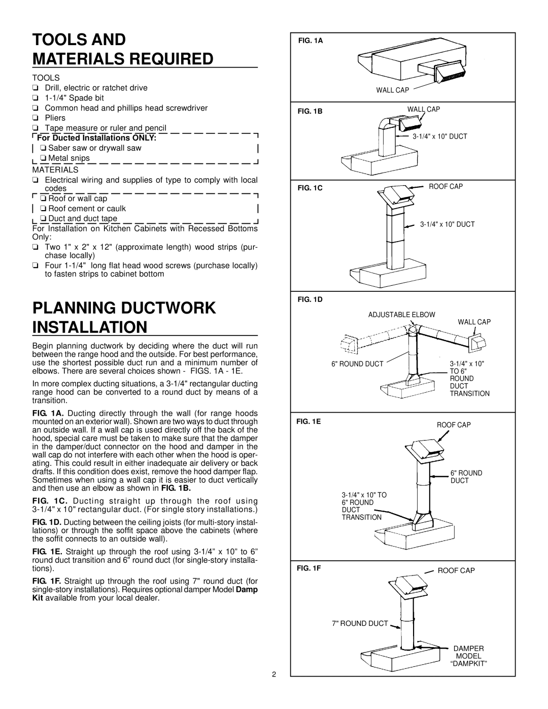
Begin planning ductwork by deciding where the duct will run between the range hood and the outside. For best performance, use the shortest possible duct run and a minimum number of elbows. There are several choices shown - FIGS. 1A - 1E.
In more complex ducting situations, a
FIG. 1A. Ducting directly through the wall (for range hoods mounted on an exterior wall). Shown are two ways to duct through an outside wall. If a wall cap is used directly off the back of the hood, special care must be taken to make sure that the damper in the damper/duct connector on the hood and damper in the wall cap do not interfere with each other when the hood is oper- ating. This could result in either inadequate air delivery or back drafts. If this condition does exist, remove the hood damper flap. Sometimes when using a wall cap it is easier to duct vertically and then use an elbow as shown in FIG. 1B.
FIG. 1C. Ducting straight up through the roof using 3-1/4" x 10" rectangular duct. (For single story installations.)
FIG. 1D. Ducting between the ceiling joists (for multi-story instal- lations) or through the soffit space above the cabinets (where the soffit connects to an outside wall).
FIG. 1E. Straight up through the roof using 3-1/4” x 10” to 6” round duct transition and 6" round duct (for single-story installa- tions).
FIG. 1F. Straight up through the roof using 7" round duct (for single-story installations). Requires optional damper Model Damp Kit available from your local dealer.
2
FIG. 1A
WALL CAP
FIG. 1B | WALL CAP | |
|
| |
|
|
|
FIG. 1C | ROOF CAP |
FIG. 1D
ADJUSTABLE ELBOW
|
| WALL CAP |
6" ROUND DUCT |
| |
| ||
| ||
|
| TO 6" |
|
| ROUND |
|
| DUCT |
|
| TRANSITION |
|
|
|
FIG. 1E |
| ROOF CAP |
|
| |
|
| 6" ROUND |
|
| DUCT |
|
| |
6" ROUND |
|
|
DUCT |
|
|
TRANSITION |
|
|
|
|
|
FIG. 1F |
| ROOF CAP |
7" ROUND DUCT |
|
|
|
| DAMPER |
|
| MODEL |
|
| “DAMPKIT” |