INSTALLING THE RANGE HOOD
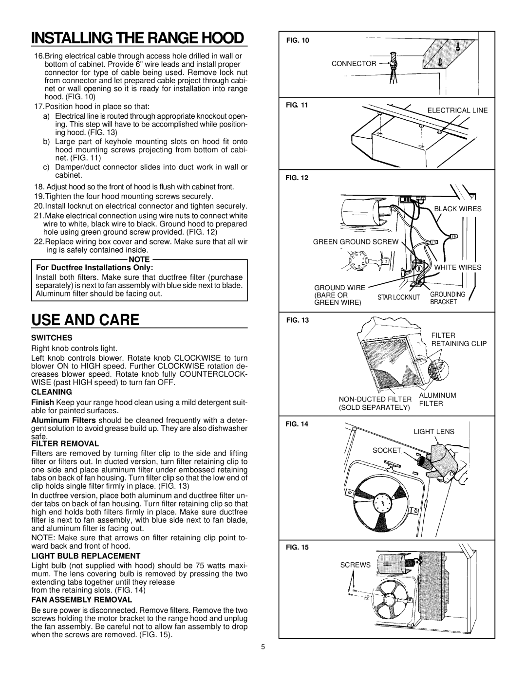
16.Bring electrical cable through access hole drilled in wall or bottom of cabinet. Provide 6" wire leads and install proper connector for type of cable being used. Remove lock nut from connector and let prepared cable project through cabi- net or wall opening so it is ready for installation into range hood. (FIG. 10)
17.Position hood in place so that:
a)Electrical line is routed through appropriate knockout open- ing. This step will have to be accomplished while position- ing hood. (FIG. 13)
b)Large part of keyhole mounting slots on hood fit onto hood mounting screws projecting from bottom of cabi- net. (FIG. 11)
c)Damper/duct connector slides into duct work in wall or cabinet.
18.Adjust hood so the front of hood is flush with cabinet front. 19.Tighten the four hood mounting screws securely. 20.Install locknut on electrical connector and tighten securely.
21.Make electrical connection using wire nuts to connect white wire to white, black wire to black. Ground hood to prepared hole using green ground screw provided. (FIG. 12)
22.Replace wiring box cover and screw. Make sure that all wir ing is safely contained inside.
NOTE
For Ductfree Installations Only:
Install both filters. Make sure that ductfree filter (purchase separately) is next to fan assembly with blue side next to blade. Aluminum filter should be facing out.
USE AND CARE
SWITCHES
Right knob controls light.
Left knob controls blower. Rotate knob CLOCKWISE to turn blower ON to HIGH speed. Further CLOCKWISE rotation de- creases blower speed. Rotate knob fully COUNTERCLOCK- WISE (past HIGH speed) to turn fan OFF.
CLEANING
Finish Keep your range hood clean using a mild detergent suit- able for painted surfaces.
Aluminum Filters should be cleaned frequently with a deter- gent solution to avoid grease build up. They are also dishwasher safe.
FILTER REMOVAL
Filters are removed by turning filter clip to the side and lifting filter or filters out. In ducted version, turn filter retaining clip to one side and place aluminum filter under embossed retaining tabs on back of fan housing. Turn filter clip so that the low end of clip holds single filter firmly in place. (FIG. 13)
In ductfree version, place both aluminum and ductfree filter un- der tabs on back of fan housing. Turn filter retaining clip so that high end holds both filters firmly in place. Make sure ductfree filter is next to fan assembly, with blue side next to fan blade, and aluminum filter is facing out.
NOTE: Make sure that arrows on filter retaining clip point to- ward back and front of hood.
LIGHT BULB REPLACEMENT
Light bulb (not supplied with hood) should be 75 watts maxi- mum. The lens covering bulb is removed by pressing the two extending tabs together until they release
from the retaining slots. (FIG. 14)
FAN ASSEMBLY REMOVAL
Be sure power is disconnected. Remove filters. Remove the two screws holding the motor bracket to the range hood and unplug the fan assembly. Be careful not to allow fan assembly to drop when the screws are removed. (FIG. 15).
FIG. 10
CONNECTOR
FIG. 11
ELECTRICAL LINE
FIG. 12 |
|
|
|
|
|
|
|
|
|
|
| ||
|
|
|
|
|
|
|
|
|
|
| |||
|
|
|
|
|
|
|
| BLACK | WIRES |
| |||
|
|
|
|
|
|
|
|
|
|
|
| ||
|
|
|
|
|
|
|
|
|
|
| |||
GREEN | GROUND SCREW |
|
|
|
|
|
|
|
| ||||
|
|
|
|
|
|
|
|
|
|
|
|
|
|
|
|
|
|
|
|
|
|
|
| ||||
|
|
|
|
|
|
|
|
| WHITE WIRES | ||||
|
|
|
|
|
|
|
|
|
|
|
|
|
|
|
|
|
|
|
|
|
|
|
|
|
|
|
|
GROUND | WIRE |
|
|
|
|
|
|
|
|
|
|
| |
|
|
|
|
| GROUNDING |
|
|
| |||||
(BARE OR |
| STAR | LOCKNUT |
|
|
|
| ||||||
GREEN WIRE) |
|
|
|
|
| BRACKET |
|
|
| ||||
|
|
|
|
|
|
|
|
|
|
|
|
|
|
FIG. 13
FILTER
RETAINING CLIP
FIG. 14
LIGHT LENS
SOCKET
FIG. 15
SCREWS
5