Chapter 4 Jumpers and LED’s
4 Jumpers and LED’s
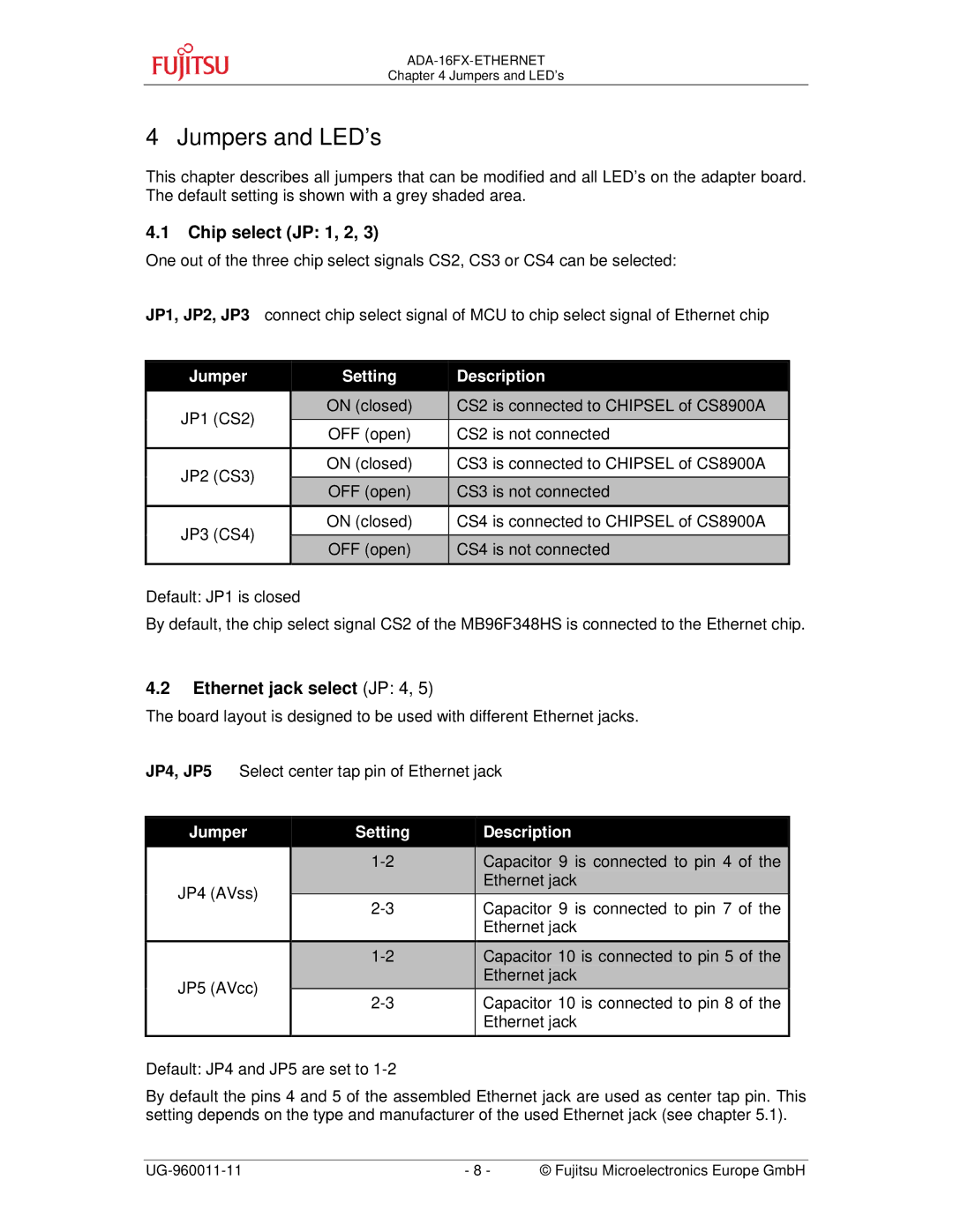
This chapter describes all jumpers that can be modified and all LED’s on the adapter board. The default setting is shown with a grey shaded area.
4.1Chip select (JP: 1, 2, 3)
One out of the three chip select signals CS2, CS3 or CS4 can be selected:
JP1, JP2, JP3 connect chip select signal of MCU to chip select signal of Ethernet chip
| Jumper |
| Setting | Description |
|
|
|
|
|
| JP1 (CS2) |
| ON (closed) | CS2 is connected to CHIPSEL of CS8900A |
|
| OFF (open) | CS2 is not connected | |
|
|
| ||
|
|
|
|
|
| JP2 (CS3) |
| ON (closed) | CS3 is connected to CHIPSEL of CS8900A |
|
|
|
| |
|
| OFF (open) | CS3 is not connected | |
|
|
| ||
| JP3 (CS4) |
| ON (closed) | CS4 is connected to CHIPSEL of CS8900A |
|
|
|
| |
|
| OFF (open) | CS4 is not connected | |
|
|
| ||
|
|
|
|
|
Default: JP1 is closed
By default, the chip select signal CS2 of the MB96F348HS is connected to the Ethernet chip.
4.2Ethernet jack select (JP: 4, 5)
The board layout is designed to be used with different Ethernet jacks.
JP4, JP5 Select center tap pin of Ethernet jack
| Jumper | Setting | Description | |
|
|
|
|
|
|
|
| Capacitor 9 is connected to pin 4 of the | |
| JP4 (AVss) |
|
| Ethernet jack |
|
| Capacitor 9 is connected to pin 7 of the | ||
|
|
| ||
|
|
|
| Ethernet jack |
|
|
|
|
|
|
|
| Capacitor 10 is connected to pin 5 of the | |
| JP5 (AVcc) |
|
| Ethernet jack |
|
| Capacitor 10 is connected to pin 8 of the | ||
|
|
| ||
|
|
|
| Ethernet jack |
|
|
|
|
|
Default: JP4 and JP5 are set to
By default the pins 4 and 5 of the assembled Ethernet jack are used as center tap pin. This setting depends on the type and manufacturer of the used Ethernet jack (see chapter 5.1).
- 8 - | © Fujitsu Microelectronics Europe GmbH |
