3.6 BK (Break-in) Connection
BK
Necessary parts
The BK function requires the CONTROL Kit, which consists of the CONTROL Board, con- nector assy., gasket and washer. Install the board following the illustration on page
Contents of CONTROL Kit OP05-41 (Code no. 005-920-330)
Name | Type | Code No. | Qty |
|
|
|
|
CONTROL PCB | 05P0459 | 1 | |
|
|
|
|
Gasket (3) | 1 | ||
|
|
|
|
Connector Assy. | 05S0846 | 1 | |
|
|
|
|
Washer | 16.2x22.0x0.5 | 1 | |
|
|
|
|
3.7 Telex Filter (Bandpass Filter)
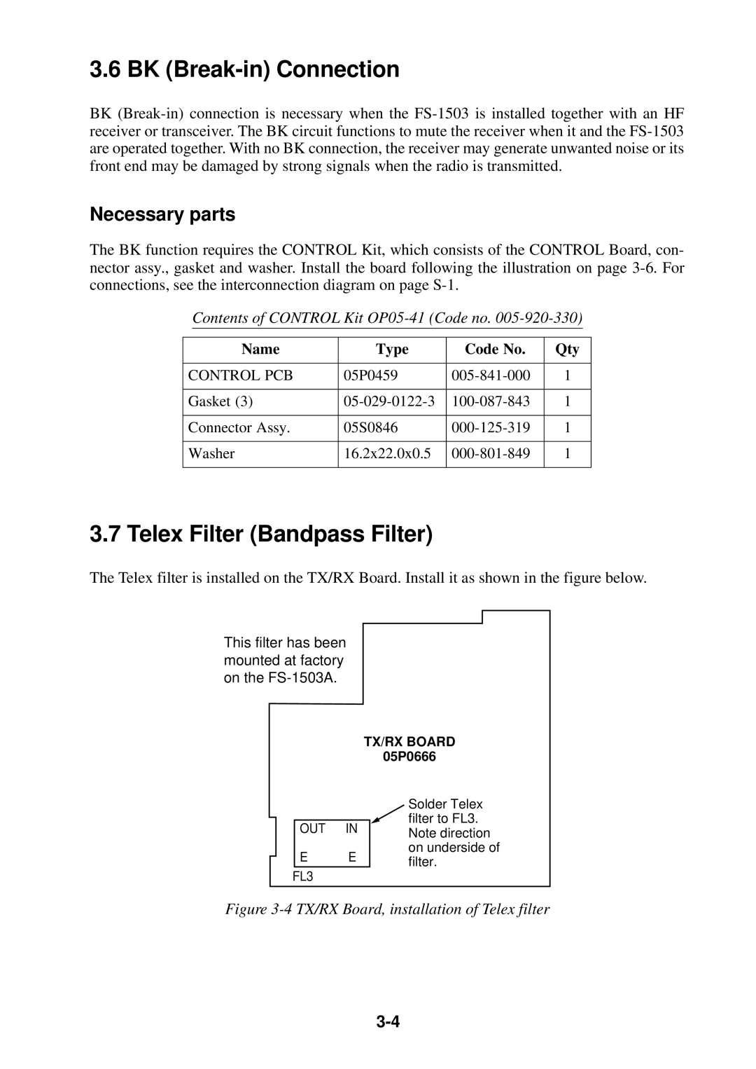
The Telex filter is installed on the TX/RX Board. Install it as shown in the figure below.
This filter has been mounted at factory on the
TX/RX BOARD
05P0666
OUT IN
EE
FL3
Solder Telex filter to FL3. Note direction on underside of filter.