Manuals
/
Furuno
/
TV and Video
/
Flat Panel Television
Furuno
MU-170C
manual
Wiring, Display unit bottom view
Models:
MU-170C
1
12
65
65
Download
65 pages
52.43 Kb
9
10
11
12
13
14
15
16
Troubleshooting
Parts list
Signal
Wiring
Maintenance
5. キーを押して、resetを選びます。
Setting battery
Adjustments
VIDEO Setting
Remote Controller Setting
Page 12
Image 12
Page 11
Page 13
Page 12
Image 12
Page 11
Page 13
Contents
MU-170C
取 扱 説 明 書
OPERATORS MANUAL
17型カラーLCD表示器
IMPORTANT NOTICE
SAFETY INSTRUCTIONS
Safety Instructions for the Operator
Safety Instructions for the Installer
Use the proper fuse and power cable
TABLE OF CONTENTS
SP-1
Declaration of Conformity
Features
FOREWORD
A Word to the Owner of the MU-170C
SYSTEM CONFIGURATION
Resolution
Signal
About the TFT LCD
EQUIPMENT LISTS
Standard supply
Option
Name
1. MOUNTING
1.1 Display Unit
Flush mounting
Desktop mounting
Desktop mounting
1.2 Remote Controller
Setting battery
Writing the device name on the label
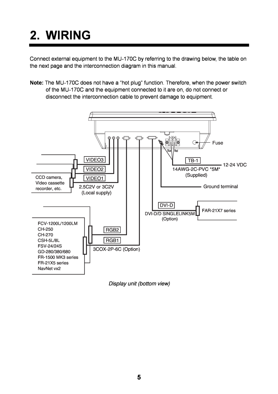
2. WIRING
Display unit bottom view
Grounding
Port
Used cable
Connectable Equipment
3. ADJUSTMENTS
3.1 RGB/DVI Setting
Menu item
Function
5500K/6500K/7000K/8000K
Available range
3.2 VIDEO Setting
VIDEO1 2 or 3 setting menu
Picture-in-picture window
3.3 Menu Window Setting
3.3.1 Adjusting the menu window
OFF Blue
3.3.2 Changing the signal name
Signal name area
3.4 Remote Controller Setting
SYSTEM menu
4. OPERATION
4.1 Controls
Power key
Display unit
Remote controller
Key name
Function
4.2 Adjusting Display Brilliance
BRILL
4.3 Choosing Source for Main Picture
RGB1
RGB2 DVI VIDEO1 VIDEO2 VIDEO3
4.4 Choosing Source for Picture-in-Picture
VIDEO1
VIDEO2 VIDEO3 OFF
5. MAINTENANCE, TROUBLESHOOTING
5.1 Maintenance
Routine maintenance
ELECTRICAL SHOCK HAZARD
5.2 Troubleshooting
Fuse replacement
Battery replacement
LCD replacement
5.3 Clearing the Memory
DEFAULT RESET
SPECIFICATIONS OF MULTI-PURPOSE LCD DISPLAY MU-170C
FURUNO
POWER SUPPLY
GENERAL
EC Declaration of Conformity
PACKING
LIST
MU-170C
付属品表
SPARE PARTS LIST FOR
NAME OF
OUTLINE
PART
Page
Page
魚群探知機 ECHO SOUNDER
SONAR
RADAR
C2034-C01-A
FURUNO 17 型カラーLCD 表示器 MU-170C 仕 様
1.総合
2.電源
3.環境条件
5.3 オールクリア
5. キーを押して、resetを選びます。
オールクリアを行って内部の設定を工場出荷状態に戻すことができます。
1. MENUキーを押して、メニューを表示します。 2. キーを押して、SYSTEMを選びます。
5.2 故障かなと思ったら
ヒューズの交換
電池の交換
LCD 交換の目安
5. 保守点検
5.1 ふだんの保守点検
本機の性能を維持するために、定期的に次の項目を点検してください。 表示器底面のコネクタが確実に接続されているか。
アース端子が錆びていないか、また、アース線が確 実に接地されているか。 表示器上にほこりや汚れはないか。ある場合は柔ら かい布でふき取る。
4.4 PIP ウィンドウの選択
注 1 OSDメニューのPIP SW TIMEを「5~20」に設定すると、PIP ウィンドウ上に VIDEO1、
4.3 入力信号の選択
画面いっぱいに表示させる入力信号を選びます。
1. DISPキーを押して、入力信号ウィンドウを表示します。
入力信号ウィンドウ 2. またはキーを押して、入力信号を選びます。
4.2 輝度の調整
表示器の輝度を調整します。
5 秒間キー操作を行わなければ、自動的にウィンドウは消えます。
BRILLキーを連続的に押しても調整することができます。
リモコン
リモコンのキー説明
キーの名称
PIP ウィンドウについては 3.2 節を参照
4. 取扱い
4.1 操作キー
電源キー()
電源をオン、オフします。
3.4 リモコンの設定
INFRARED REMOTEで表示器とリモコンの識別符号(ID)を設定します。ID は「A」~「D」 の 4 種類です。
4. 表示器のリモコン受光部に向けて、リモコンのいずれかのキーを押します。
INFRARED REMOTEの行のの中に、現在のリモコンの ID が表示されます。
3.3.2 信号名の変更
「RGB1」から「VIDEO3」の入力信号名を装置の名前等、判りやすい名前に変更できます。
変更した文字は、入力信号ウィンドウ(17 ページ参照)および PIP 設定ウィンドウ(18 ページ 参照)に表示されます。
1. MENUキーを押して、メニューを表示します。 2. またはキーを押して、OSDを選びます。
3.3 メニュー表示の設定
3.3.1 メニューの調整
メニューの表示位置や表示方法を設定します。
3. またはキーを押して、設定する項目を選びます。 4. またはキーを押して、設定内容を調整します。
設定項目の内容
PIPSIZE
画面サイズ 35mmx27mm(1)←→237mmx189mm(10)
CONTRAST
3.2 VIDEO1、VIDEO2、VIDEO3 信号の設定
PIP ウィンドウ 1. 入力信号ウィンドウで設定する信号を選びます(4.3 節参照)。
2. MENUキーを押して、メニューを表示します。
項目に応じたメニューが現れます。VIDEO1~VIDEO3は同じメニュー内容です。
2 文字がぼやけているときは、PHASEとSHARPNESSを調整してください。
1 VGA、SVGA、XGA 入力信号の場合、表示器の画面と入力信号との縦横比が異なるため、
NORMAL*1
3. 装備後の設定
3.1 RGB1、RGB2、DVI 信号の設定
本機に接続している機器に応じて、信号の設定を行います。
RGB1、RGB2、DVI からの入力信号の表示方法を設定します。
Page
2. 結線
注 ホットプラグ機能はありませんので、本機と接続機器が電源オンの時にコネクタの抜き 差しは行わないでください。破壊される恐れがあります。
表示器(底面)
1.2 リモコン
電池を入れる
貼りマークに記入する
PIP2
卓上装備
000-153-819)が必要です。
埋込み装備
1. 支給の型紙を使って、装備場所に穴を開けます。 2. 表示器のハードカバー、4 個のパネルカバーを取り外して、取付穴にはめ込みます。
3. 表示器本体の正面から 4 本の+トラスタッピンネジ(5x40,付属品として支給)で固定し ます。
注)六角ボルトを使用する場合、壁から 10mm 突出する長さのボルトを使用してください。 埋込み装備
1. 取付け要領
1.1 表示器
本書の外寸図を参照してください。
注)LCD 管面は壊れやすいガラス素材でできています。強い衝撃や圧力を加えないでくださ い。
オプション
システム構成
接続可能機種
信号形式
1 縦型は未対応。 2 VGA、SVGA、XGA の信号を入力すると、縦横比が異なるため、円の縦横が歪んで楕円
はじめに
本機の特徴
輝度調整機能付き(最大輝度 1000cd/, 最小輝度 2cd/以下) (昼夜を問わず快適な明るさでご覧になれます) 横置き装備
ピクチャーインピクチャー機能
取付け要領
Page
安全にお使いいただくために
必ずお守りください
「このページは空白です。」
重要なお知らせ
取扱説明書の一部または全部の転載、複写は著作権者である当社の許諾が必要です。無断転 載することを固くお断りします。
本書を紛失または汚損されたときは、お買い上げの販売店または最寄りの当社各支店・営業 所でお買い求めください。
製品の仕様ならびに取扱説明書の内容は予告なく変更することがあります。
Top
Page
Image
Contents