004 INSTALLATION
INSTALLATION
IF ANY MODIFICATION TO THE VESSEL IS REQUIRED, SUCH AS DRILLING HOLES ETC FUSION RECOMMENDS CONSULTATION WITH YOUR BOAT DEALER OR MANUFACTURER BEFOREHAND.
MENU STRUCTURE
ROOT MENU
017 MENU STRUCTURE
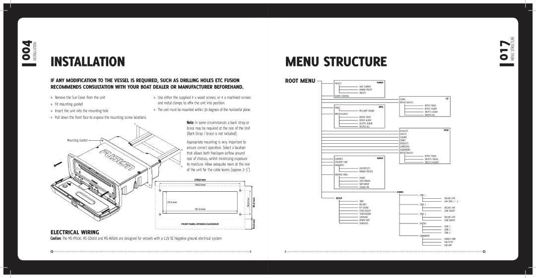
»Remove the Sun Cover from the unit
»Fit mounting gasket
»Insert the unit into the mounting hole
»Pull down the front face to expose the mounting screw locations.
Mounting Gasket 
»Use either the supplied 4 x wood screws, or 4 x machined screws and metal clamps to affix the unit into position.
»The unit must be mounted within 30 degrees of the horizontal plane.
Note: In some circumstances a back strap or brace may be required at the rear of the Unit (Back Strap / brace is not included).
Appropriate mounting is very important to ensure correct operation. Select a location that allows both free/open airflow around rear of chassis, whilst minimizing exposure to moisture. Allow adequate room at the rear of the unit for the cable looms (approx
ELECTRICAL WIRING
Caution: The