Manuals
/
Lennox International Inc
/
Household Appliance
/
Heat Pump
Lennox International Inc
Comprehensive Guide to Lennox XP17 Heat Pump Wiring and Functionality
Models:
Dave Lennox Signature Collection XP17 System HEAT PUMPS
506586-01
1
22
54
54
Download
54 pages
9.7 Kb
19
20
21
22
23
24
25
26
Troubleshooting
Install
3A. Route Control Wires Ting
Dimension
Maintenance
TOP Grille Adjustment
Recovering Refrigerant
Unit Placement
Operating Service Valves
Using HFC−410A Weigh In Method
Page 22
Image 22
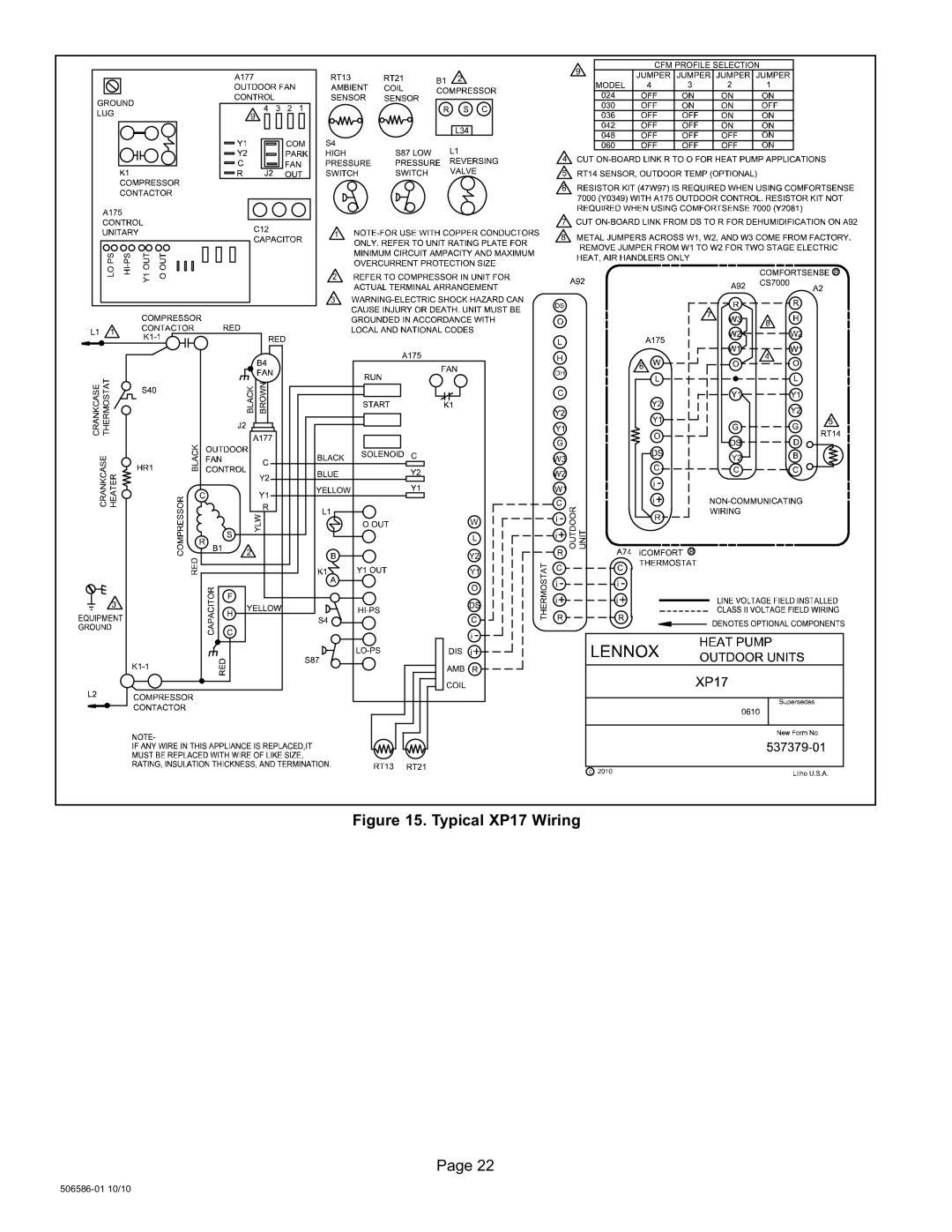
Figure 15. Typical XP17 Wiring
Page 22
506586−01 10/10
Page 21
Page 23
Page 22
Image 22
Page 21
Page 23
Contents
General
Table of Contents
Heat Pumps
Model Number Identification
Unit Dimensions −− Inches mm
Side View Access View
Base with Elongated Legs
Typical Unit Parts Arrangement
Control BOX
Operating Service Valves
Using Manifold Gauge Set
Shipping and Packing List
To Access Service Port
Operating Angle Type Service Valve
Operating Ball Type Service Valve
Reinstall Stem Cap
Recovering Refrigerant
Recovering Refrigerant from Existing System
1DISCONNECT Power
2CONNECT Manifold Gauge SET
Unit Placement
Detail a Outside Unit Placement
Placement, Slab Mounting and Stabilizing Unit
Stabilizing Unit on Uneven Surfaces
Removing and Installing Panels
Roof Mounting
Detail C
Louvered Panel Installation
Louvered Panel Removal
Detail D Detail a
New or Replacement Line Set
Refrigerant Line SET
Refrigerant Line SET From Vertical to Horizontal
Refrigerant Line SET Alling Horizontal Runs
Brazing Connections
1PIPING Panel Removal and Preparing Line SET
2CAP and Core Removal
Braze Line SET
Wrap Service Valves
Flow Nitrogen
7PREPARATION for Next Step
Flushing Line Set and Indoor Coil
Flushing Line Set and Indoor Coil
Sensing Bulb Installation
Installing Indoor Expansion Valve
Indoor Expansion Valve Installation
Equalizer Line Installation
Leak Test Line Set and Indoor Coil
Leak Test
Evacuating Line Set and Indoor Coil
S S S S
Electrical
Size Circuit and Install Disconnect
2INSTALL Thermostat
24VAC Transformer
Route Control Wires Ting
3A. Route Control Wires Ting
4ROUTE High Voltage and Ground Wires
Typical XP17 Wiring
Heat Pump Control A175 Jumpers and Terminals
Heat Pump Control AGE
Heat Pump Control A175 Jumper and Terminal Descriptions
Field Control Wiring
Flat metal jumper
Furnace Control
Unit Start−Up
Connections for Testing and Charging
Servicing Units Delivered Void of Charge
System Refrigerant
Adding or Removing Refrigerant
Cooling Mode Indoor Airflow Check
Heating Mode Indoor Airflow Check
Airflowindoor Coil
Using HFC−410A Weigh In Method
Subcooling Charging Method
Air Handler / Coil Match ups and Targeted Subcooling Values
Operating and Temperature Pressures
Psig
System Operations
Defrost System
Resistor Location Sensor Temperature / Resistance Range
Unit Sensors
Defrost Calibration Sequence of Operations
YES
Test Pin E33 Functions
S S
Low Pressure S87 Switch Operation
Or below
High Pressure Switch S4 Sequence of Operation
Input Fault or Miswire
Degrees Resistance Fahrenheit 136.3 2680
Resetting Fault and Lockout LED Codes
System Status, Fault and Lockout LED Codes
DS11 and DS14 ATUS, Fault Lockout LED Codes
DS15 and DS13 Ault Lockout LED Codes
Alert Status
Moderate Device
225ºF 107ºC Lockout
Vice removed or
Clears after
FAN Motor B4 Test Procedure
Field Configuration and Testing
Troubleshooting
FAN Motor Control A177 OPERATION,
Fan Motor Control RPM, LED Code and DC Voltage Output
Fan Motor Control Error/Fault LED Codes
Fan Motor Control Stage LED Indicator Codes
Fan Motor Control Flash and Pause Durations
FAN Motor Position Adjustment
TOP Grille or FAN Motor Mount Adjustment for FAN Clearance
TOP Grille Adjustment
Demand Begins
FAN Motor Control A177 PULSE−WIDTH Modulation PWM
Testing for External Power to Fan Motor Control
Terminal
Strip
Start
Finish
Maintenance
Snow Guard Top Cover
Homeowner
SunSource Home Energy System
Heating Mode
XP17 Start−Up and Performance Checklist
Cooling Mode
START−UP Checks
Top
Page
Image
Contents