Heat Pump Control (A175) Jumpers and Terminals
HEAT PUMP CONTROL AGE
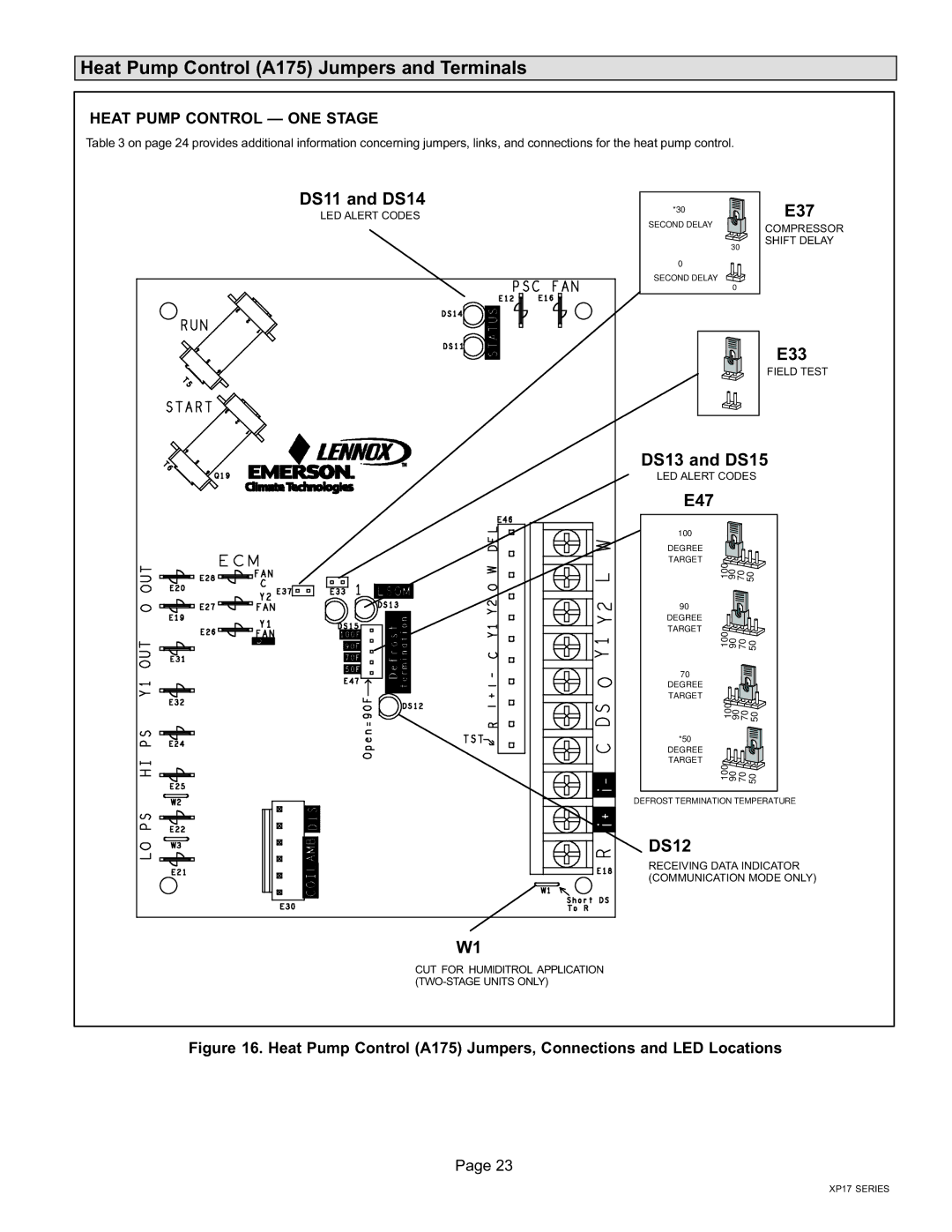
Table 3 on page 24 provides additional information concerning jumpers, links, and connections for the heat pump control.
DS11 and DS14 | *30 | |
LED ALERT CODES | ||
SECOND DELAY | ||
| ||
| 30 | |
| 0 | |
| SECOND DELAY | |
| 0 |
E37
COMPRESSOR SHIFT DELAY
E33
FIELD TEST
DS13 and DS15
LED ALERT CODES
E47
100
DEGREE
TARGET ![]()
![]()
![]()
![]()
![]()
![]()
![]() 100907050
100907050 ![]()
90 DEGREE
TARGET ![]()
![]()
![]()
![]()
![]()
![]() 10090 70 50
10090 70 50 ![]()
70
DEGREE
TARGET ![]()
![]()
![]()
![]()
![]()
![]() 1009070 50
1009070 50![]()
![]()
*50
DEGREE
TARGET ![]()
![]()
![]()
![]()
![]()
![]() 10090 70 50
10090 70 50![]()
DEFROST TERMINATION TEMPERATURE
DS12
RECEIVING DATA INDICATOR (COMMUNICATION MODE ONLY)
W1
CUT FOR HUMIDITROL APPLICATION (TWO−STAGE UNITS ONLY)
Figure 16. Heat Pump Control (A175) Jumpers, Connections and LED Locations
Page 23
XP17 SERIES