Lennox International Inc 506586-01 installation instructions Control Box, Page

Models: Dave Lennox Signature Collection XP17 System HEAT PUMPS 506586-01

1 54
Download 54 pages 9.7 Kb
Page 48
Image 48
Manual background

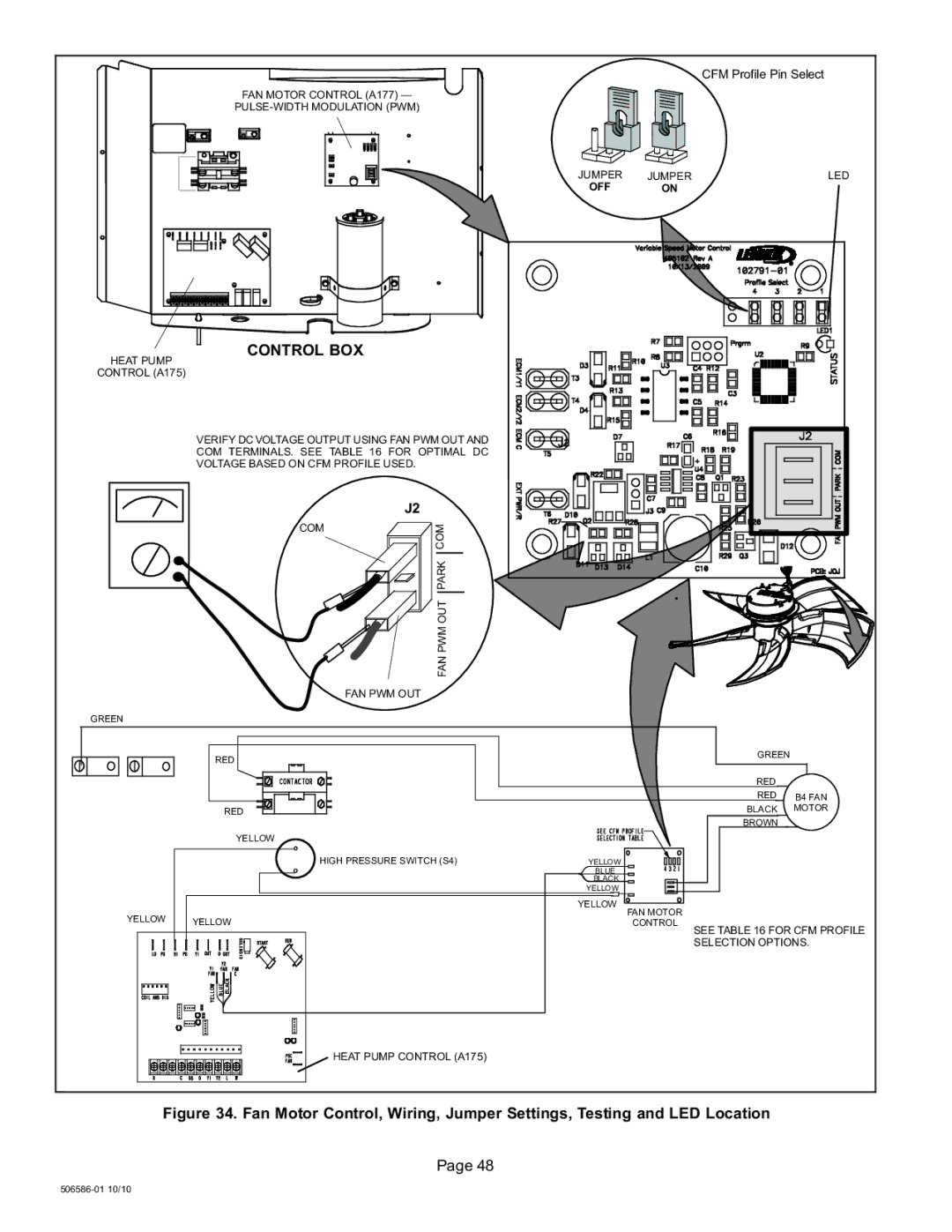
FAN MOTOR CONTROL (A177) PULSE−WIDTH MODULATION (PWM)

CFM Profile Pin Select

JUMPER

JUMPER

LED

OFF

ON


CONTROL BOX

HEAT PUMP

CONTROL (A175)

GREEN

YELLOW

VERIFY DC VOLTAGE OUTPUT USING FAN PWM OUT AND COM TERMINALS. SEE TABLE 16 FOR OPTIMAL DC VOLTAGE BASED ON CFM PROFILE USED.


J2

COM

COM


PARK


FAN PWM OUT


FAN PWM OUT

RED

RED

YELLOW

HIGH PRESSURE SWITCH (S4)

YELLOW

J2

GREEN


RED


RED

B4 FAN


BLACK MOTOR

BROWN


YELLOW

BLUE

BLACK

YELLOW

YELLOW

FAN MOTOR

CONTROL

SEE TABLE 16 FOR CFM PROFILE

SELECTION OPTIONS.

HEAT PUMP CONTROL (A175)

Figure 34. Fan Motor Control, Wiring, Jumper Settings, Testing and LED Location

Page 48

506586−01 10/10

Page 48
Image 48
Lennox International Inc 506586-01, Dave Lennox Signature Collection XP17 System HEAT PUMPS Control Box, Page

FAQ

What is the purpose of the fan motor control?

The fan motor control is used to regulate the fan speed and airflow in the heat pump system.

How do I verify the DC voltage output?

You can verify the DC voltage output by using the fan PWM out and COM terminals. Refer to Table 16 for optimal DC voltage based on the CFM profile used.

Where can I find the wiring, jumper settings, and LED location?

The wiring, jumper settings, and LED location can be found in Figure 34 on page 4850658601 of the manual.