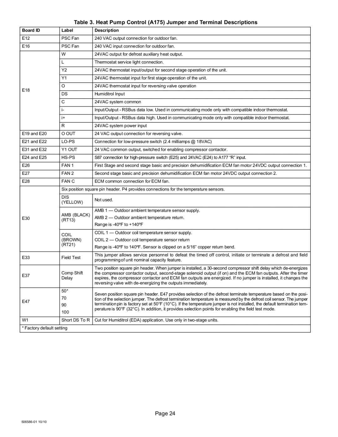
Table 3. Heat Pump Control (A175) Jumper and Terminal Descriptions
Board ID | Label | Description | |
|
|
| |
E12 | PSC Fan | 240 VAC output connection for outdoor fan. | |
|
|
| |
E16 | PSC Fan | 240 VAC input connection for outdoor fan. | |
|
|
| |
| W | 24VAC output for defrost auxiliary heat output. | |
|
|
| |
| L | Thermostat service light connection. | |
|
|
| |
| Y2 | 24VAC thermostat input/output for second stage operation of the unit. | |
|
|
| |
| Y1 | 24VAC thermostat input for first stage operation of the unit. | |
|
|
| |
| O | 24VAC thermostat input for reversing valve operation | |
E18 |
|
| |
DS | Humiditrol Input | ||
| |||
|
|
| |
| C | 24VAC system common | |
|
|
| |
| i− | Input/Output − RSBus data low. Used in communicating mode only with compatible indoor thermostat. | |
|
|
| |
| i+ | Input/Output − RSBus data high. Used in communicating mode only with compatible indoor thermostat. | |
|
|
| |
| R | 24VAC system power input | |
|
|
| |
E19 and E20 | O OUT | 24 VAC output connection for reversing valve. | |
|
|
| |
E21 and E22 | LO−PS | Connection for low−pressure switch (2.4 milliamps @ 18VAC) | |
|
|
| |
E31 and E32 | Y1 OUT | 24 VAC common output, switched for enabling compressor contactor. | |
|
|
| |
E24 and E25 | HS−PS | S87 connection for high−pressure switch (E25) and 24VAC (E24) to A177 R" input. | |
|
|
| |
E26 | FAN 1 | First Stage and second stage basic and precision dehumidification ECM fan motor 24VDC output connection 1. | |
|
|
| |
E27 | FAN 2 | Second stage basic and precision dehumidification ECM fan motor 24VDC output connection 2. | |
|
|
| |
E28 | FAN C | ECM common connection for ECM fan. | |
|
|
| |
| Six position square pin header. P4 provides connections for the temperature sensors. | ||
|
|
| |
| DIS | Not used. | |
| (YELLOW) | ||
|
| ||
|
|
| |
|
| AMB 1 | |
E30 | AMB (BLACK) | AMB 2 | |
| (RT13) |
| |
|
| Range is −40ºF to +140ºF | |
|
|
| |
| COIL | COIL 1 | |
|
| ||
| (BROWN) | COIL 2 | |
| (RT21) | Range is −40ºF to 140ºF. Sensor is clipped on a 5/16" copper return bend. | |
|
| ||
|
|
| |
E33 | Field Test | This jumper allows service personnel to defeat the timed off control, initiate or terminate a defrost and field | |
programming of unit nominal capacity feature. | |||
|
| ||
|
|
| |
|
| Two position square pin header. When jumper is installed, a 30−second compressor shift delay which de−energizes | |
E37 | Comp Shift | the compressor contactor output, second−stage solenoid output (if on) and the ECM fan outputs. After the timer | |
Delay | expires, the compressor contactor and ECM fan outputs are energized. If no jumper is installed, it changes the | ||
| |||
|
| reversing valve with de−energizing the outputs immediately. | |
|
|
| |
| 50* | Seven position square pin header. E47 provides selection of the defrost terminate temperature based on the posi- | |
| 70 | ||
E47 | tion of the selection jumper. The defrost termination temperature is measured by the defrost coil sensor. The jumper | ||
| |||
90 | termination pin is factory set at 50°F (10°C). If the temperature jumper is not installed, the default termination tem- | ||
| |||
| perature is 90°F (32°C). In addition, it provides selection points for enabling the field test mode. | ||
| 100 | ||
|
| ||
|
|
| |
W1 | Short DS To R | Cut for Humiditrol (EDA) application. Use only in two−stage units. | |
|
|
| |
* Factory default setting |
| ||
|
|
| |
Page 24
506586−01 10/10