Lennox International Inc Dave Lennox Signature Collection XP17 System HEAT PUMPS Control Box

Models: Dave Lennox Signature Collection XP17 System HEAT PUMPS 506586-01

1 54
Download 54 pages 9.7 Kb
Page 49
Image 49
Manual background

FAN MOTOR CONTROL (A177) PULSE−WIDTH MODULATION (PWM)

CONTROL BOX

INPUT VOLTAGES DURING DEMAND

ECM/Y1 ONLY − 24VDC

YELLOW WIRE

HEAT PUMP

BLUE WIRE

CONTROL (A175)


24

BLACK WIRE

VDC VAC

ONE YELLOW WIRE FROM PS (E24) TERMINAL ON HEAT PUMP


CONTROL (A175) AND SECOND YELLOW WIRES ON PIGGYBACK

EXT PWR/R (24VAC INPUT


TERMINALS GOES TO S4 HIGH PRESSURE SWITCH.


DURING DEMAND ONLY)


GREEN


RED

GREEN


RED


RED

B4 FAN


RED

BLACK MOTOR


BROWN


YELLOW


S4 HIGH PRESSURE SWITCH

YELLOW


BLUE


BLACK


YELLOW

YELLOW

YELLOW YELLOW

FAN MOTOR

CONTROL

SEE TABLE 16 FOR CFM PROFILE

SELECTION OPTIONS.

HEAT PUMP CONTROL

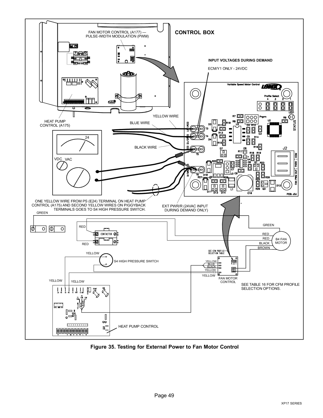
Figure 35. Testing for External Power to Fan Motor Control

Page 49

XP17 SERIES
Page 49
Image 49
Lennox International Inc Dave Lennox Signature Collection XP17 System HEAT PUMPS, 506586-01 Control Box, Page

FAQ

What is the purpose of the fan motor control?

The fan motor control regulates the operation of the fan motor in the heat pump system.

What are the input voltages during demand for the heat pump system?

The input voltages during demand are 24VDC and VAC.

How can I test for external power to the fan motor control?

Refer to Figure 35 on page 49 of the XP17 Series manual for instructions on testing for external power to the fan motor control.