
620OS specifications
The GBC 620OS is an innovative and versatile binding machine that stands out in the realm of document finishing solutions. Designed for both professional and office environments, it combines efficiency with a range of advanced features tailored to meet the diverse needs of users.One of the main features of the GBC 620OS is its ability to handle various binding styles. It supports different types of binding, including comb, wire, and thermal binding, allowing users to choose the method that best fits their document presentation needs. This versatility ensures that both simple reports and sophisticated presentations can be assembled with ease.
The GBC 620OS is equipped with a user-friendly interface, making it accessible for both experienced users and beginners. The machine features intuitive controls that guide users through the binding process, reducing the learning curve associated with more complex binding machines. Furthermore, it incorporates a built-in document thickness sensor that automatically adjusts the binding settings for optimal performance.
In terms of productivity, the GBC 620OS is designed to maximize efficiency. It boasts a high-speed punching mechanism, which allows users to punch multiple sheets in a single operation. This feature is particularly beneficial for high-volume binding tasks, saving time and effort during the document preparation process. Additionally, the machine has a large binding capacity, capable of handling documents with a thickness of up to 500 sheets, making it suitable for a wide range of applications.
Another key characteristic of the GBC 620OS is its robust construction. Built with durability in mind, this binding machine is designed to withstand the rigors of frequent use, ensuring long-term reliability. The high-quality materials used in its construction contribute to reduced maintenance needs, making it a cost-effective choice for organizations looking to enhance their binding capabilities.
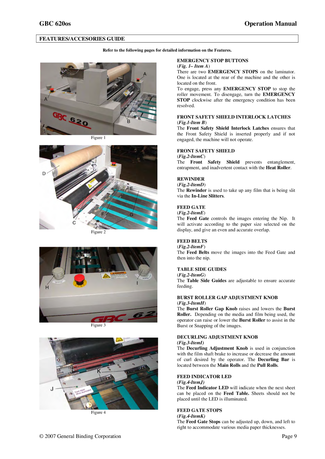
The GBC 620OS also emphasizes safety features designed to protect the user. It is equipped with safety mechanisms that prevent accidental operation, reducing the risk of injuries during use. Additionally, the machine's compact design allows for easy storage and mobility, ensuring it can fit into various workspace configurations.
In summary, the GBC 620OS is a powerful and versatile binding machine that combines user-friendly features, advanced technology, and durable construction. Its ability to accommodate multiple binding styles and high-volume tasks makes it an essential tool for any organization looking to improve its document finishing processes. Whether for reports, presentations, or other important documents, the GBC 620OS delivers consistent results with a professional touch.