Each Line on a Separate Modular Jack
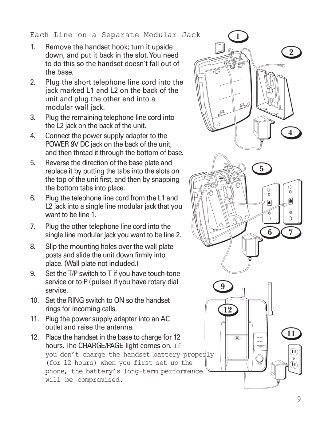
1.Remove the handset hook; turn it upside down, and put it back in the slot.You need to do this so the handset doesn’t fall out of
the base.
2.Plug the short telephone line cord into the jack marked L1 and L2 on the back of the unit and plug the other end into a modular wall jack.
3.Plug the remaining telephone line cord into the L2 jack on the back of the unit.
4.Connect the power supply adapter to the POWER 9V DC jack on the back of the unit, and then thread it through the bottom of base.
5.Reverse the direction of the base plate and replace it by putting the tabs into the slots on the top of the unit first, and then by snapping
the bottom tabs into place.
6.Plug the telephone line cord from the L1 and L2 jack into a single line modular jack that you want to be line 1.
7. Plug the other telephone line cord into the single line modular jack you want to be line 2.
8.Slip the mounting holes over the wall plate posts and slide the unit down firmly into place. (Wall plate not included.)
9.Set the T/P switch to T if you have
10.Set the RING switch to ON so the handset rings for incoming calls.
11.Plug the power supply adapter into an AC outlet and raise the antenna.
12.Place the handset in the base to charge for 12 hours.The CHARGE/PAGE light comes on. If
you don’t charge the handset battery properly (for 12 hours) when you first set up the phone, the battery’s
1
2
4
5
6 7
9
12
11
![]() LINE 1
LINE 1
![]() LINE 2
LINE 2
![]() CHANRGE/
CHANRGE/
PAGE
PAGE
9