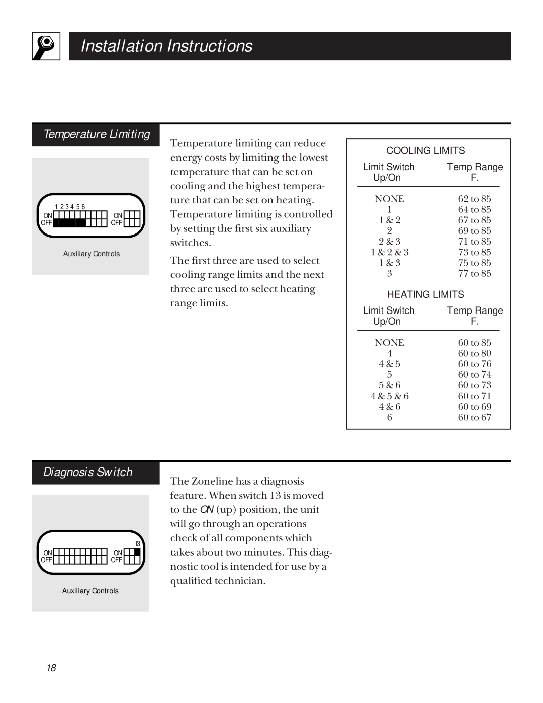
5100 specifications
The GE 5100 is a state-of-the-art gas turbine engine developed by General Electric, designed to offer unparalleled efficiency and reliability for power generation. This advanced engine has been engineered with a focus on innovative technology and cutting-edge materials, making it a favorable choice for utility companies and independent power producers around the globe.One of the main features of the GE 5100 is its remarkable efficiency. With a simple cycle efficiency surpassing traditional gas turbines, the GE 5100 ensures that utility providers can generate more electricity from the same amount of fuel. This is crucial in today’s energy landscape, where operational costs and environmental concerns are top priorities.
The GE 5100 employs a modular design that facilitates maintenance and reduces downtime. The engine consists of easy-to-replace modules, enabling rapid service without extensive disassembly. As a result, power plants using the GE 5100 experience enhanced availability and lower operational costs.
In terms of technology, the GE 5100 utilizes advanced aerodynamics, which optimizes airflow through the turbine and enhances its overall performance. The blade design has been refined using sophisticated computational fluid dynamics (CFD) simulations, which allow engineers to predict performance accurately while minimizing drag and maximizing thrust.
Another notable characteristic of the GE 5100 is its durability. The engine is constructed using high-performance materials that can withstand extreme temperatures and pressures. This robustness not only extends the life of the engine but also ensures reliability even in the most demanding operational environments.
Furthermore, the GE 5100 incorporates an advanced control system that enables operators to monitor performance in real-time, adjusting parameters for optimal efficiency. This level of precision helps to optimize fuel consumption while adhering to emissions regulations, making it a greener option in power generation.
In summary, the GE 5100 gas turbine engine stands out for its efficiency, modular design, advanced aerodynamics, durability, and sophisticated control systems. These features make it a compelling choice for energy providers aiming to improve their performance while remaining environmentally responsible. With the ever-evolving landscape of energy demands, the GE 5100 represents a significant leap forward in gas turbine technology, providing reliable and efficient power generation solutions globally.

