Manuals
/
GE
/
Household Appliance
/
Heat Pump
GE
5200
installation instructions
Power Connection Chart, Installation Instructions
Models:
5200
1
14
24
24
Download
24 pages
34.06 Kb
11
12
13
14
15
16
17
18
Install
Warranty
Problem
Parts and Accessories
setting.7
Care & Cleaning
How to
Safety
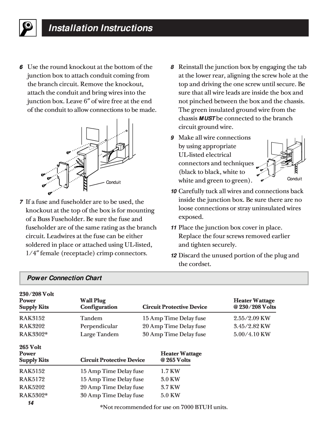
Power Connection Chart
Before You Call For Service
Page 14
Image 14
Page 13
Page 15
Page 14
Image 14
Page 13
Page 15
Contents
Installation Instructions
GE Answer Center
Important Safety Information
Important Electrical Safety
Welcome
Before using your Zoneline
800.626.2000
Start Here
READ ALL SAFETY INFORMATION BEFORE USING
SAVE THESE INSTRUCTIONS
Replacing an existing unit?
IMPORTANT SAFETY INFORMATION
1Temp Control
The controls on your Zoneline
Operating Instructions
2Fan, Mode & Operation
4Air Direction
Energy Tips
3Ventilation Control
Vent control
Operating Instructions
Other Zoneline features
About Your Heat Pump
To Remove the Room Cabinet
1 2 3 4 5 6 7 8 9 A BCDE
Fan Switch
setting.7
Auxiliary Controls
Base Pan
Care & Cleaning
Outdoor Coils
Room Cabinet and Case
Air Filters
Keeping these filters clean will
To clean the air filters
Operating Tip
Replacing an Existing Unit?
Installation Instructions
Read carefully
Use the correct wall case
Important Notes
Important Electrical Safety-ReadCarefully
YOU WILL NEED Universal power connector kit
Zoneline Components
Installation Instructions
How to Connect
230/208 Volt Electrical Supply
Steps for preparing cordset for direct connection
265 Volt Electrical Supply
Power Connection Chart
Installation Instructions
Insulated Wall Case
1 Install the Wall Case and the Exterior Grille
2 Remove the Shipping Tape from the Room Cabinet
Installation Instructions
3 Install the Unit into the Wall Case
4 Replace the Room Cabinet
Electric Heat Option
Low Voltage Connectors & Auxiliary Controls
Boost Heat Option
All-TimeLow Fan
Remote Control/Wall Thermostat Class
Central Desk Control Load Shedding
Installation Instructions
Diagnosis Switch
Temperature Limiting
Noise
Things That Are Normal
Helpful Information
Explanation
If Something Goes Wrong
Before You Call For Service
Problem
Possible Causes
Heating Operation
Burning Odor at the Start of Heating Operation
Temperature Display Flashes
Before You Call For Service
On-SiteRepair Service
GE Service Numbers
Further Service
Parts and Accessories
ZONELINE WARRANTY
What Is Covered
What Is Not Covered
Staple sales slip or cancelled check here
Top
Page
Image
Contents