Physical Description
The SLP occupies a single slot in the Series 90-30 rack, communicating with the PLC CPU over the backplane to perform its many control functions. The SLP controls and accesses CPUI/O, register, and system data.
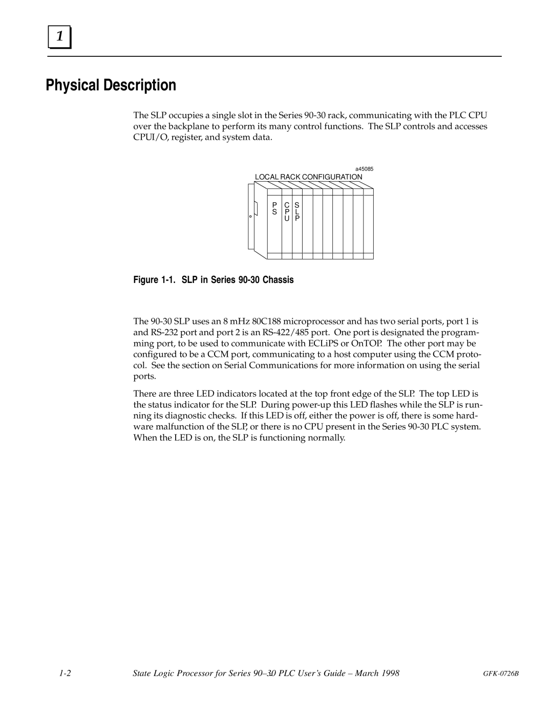
LOCAL RACK CONFIGURATION
Figure 1-1. SLP in Series 90-30 Chassis
The 90-30 SLP uses an 8 mHz 80C188 microprocessor and has two serial ports, port 1 is and RS-232 port and port 2 is an RS-422/485 port. One port is designated the program- ming port, to be used to communicate with ECLiPS or OnTOP. The other port may be configured to be a CCM port, communicating to a host computer using the CCM proto- col. See the section on Serial Communications for more information on using the serial ports.
There are three LED indicators located at the top front edge of the SLP. The top LED is the status indicator for the SLP. During power-up this LED flashes while the SLP is run- ning its diagnostic checks. If this LED is off, either the power is off, there is some hard- ware malfunction of the SLP, or there is no CPU present in the Series 90-30 PLC system. When the LED is on, the SLP is functioning normally.
1-2 | State Logic Processor for Series 90±30 PLC User's Guide ± March 1998 | GFK-0726B |
| - | |