INSTALLATION / INSTALLATION / INSTALACIÓN

Manifold / Collecteur / Colector

To Water Supply Valve

Vers le robinet d’alimentation d’eau


Hacia la válvula del suministro


de agua

Inlet


Entrée


Outlet


Entrada


Sortie


Filter Canister / Filtre à cartouche / Alojamiento del filtro

Salida

8/2.4 m

To Refrigerator

Vers le réfrigérateur

Hacia el refrigerador

Fig. 2

Step 3a. Wall Mounting

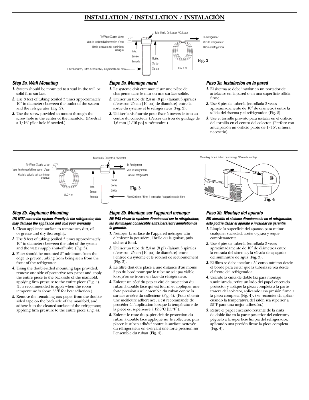
1.System should be mounted to a stud in the wall or solid firm surface.

2.Use 8 feet of tubing (coiled 3 times approximately 10″ in diameter) between the outlet of the system and the refrigerator (Fig. 2).

3.Use the screw provided to mount through the screw hole in the center of the manifold. (Pre-drill a 1/16″ pilot hole if needed.)

Étape 3a. Montage mural

1.Le système doit être monté sur une pièce de charpente dans le mur ou une surface solide.

2.Utiliser un tube de 2,4 m (8 pi) (faisant 3 spirales d’environ 25 cm [10 po] de diamètre) entre la sortie du système et le réfrigérateur (Fig. 2).

3.Utiliser la vis fournie pour fixer à travers le trou au centre du collecteur. (Percer un trou de guidage de 1,6 mm [1/16 po] si nécessaire.)

Paso 3a. Instalación en la pared

1.El sistema se debe instalar en un portador de artefactos en la pared o en una superficie sólida firme.

2.Use 8 pies de tubería (enrollada 3 veces aproximadamente de 10″ de diámetro) entre la salida del sistema y el refrigerador (Fig. 2).

3.Use el tornillo provisto para instalar en el orificio del tornillo en el centro del colector. (Perfore con anticipación un orificio piloto de 1/16″, si fuera necesario).

To Water Supply Valve

Vers le robinet d’alimentation d’eau

Hacia la válvula del suministro de agua

8/2.4 m

Manifold / Collecteur / Colector


Mounting Tape / Ruban de montage / Cinta de montaje


To Refrigerator


Vers le réfrigérateur


Hacia el refrigerador


Outlet


Inlet

Sortie

Fig. 3


Entrée

Salida


Entrada


Filter Canister / Filtre à cartouche / Alojamiento del filtro

Fig. 4


Step 3b. Appliance Mounting

DO NOT screw the system directly to the refrigerator; this may damage the appliance and void your warranty.

1.Clean appliance surface to remove any dirt, oil or grease and dry thoroughly.

2.Use 8 feet of tubing (coiled 3 times approximately 10″ in diameter) between the inlet of the system and the water supply shut-off valve (Fig. 3).

3.Filter should be mounted 5″ minimum from the edge to prevent tubing from being seen from the front of the refrigerator.

4.Using the double-sided mounting tape provided, remove one side of protective wax paper and apply the entire piece to the back side of the manifold, applying firm pressure to the entire piece (Fig. 4). (It is recommended to apply when the room temperature is above 55°F for best adhesion.).

5.Remove the remaining wax paper from the double- sided tape on the back side of the manifold, and adhere it to the cleaned surface of the refrigerator, applying firm pressure to the entire piece (Fig. 4).

Étape 3b. Montage sur l’appareil ménager

NE PAS visser le système directement sur le réfrigérateur; les dommages consécutifs entraîneraient l’annulation de la garantie.

1.Nettoyer la surface de l’appareil ménager afin d’enlever la poussière, l’huile ou la graisse, puis sécher à fond.

2.Utiliser un tube de 2,4 m (8 pi) (faisant 3 spirales d’environ 25 cm [10 po] de diamètre) entre l’entrée du système et le robinet de sectionnement (Fig. 3).

3.Le filtre doit être placé à une distance d’au moins 5 po du bord pour que le tube ne soit pas visible lorsqu’on se trouve en face du réfrigérateur.

4.Enlever un côté du papier ciré de protection du ruban à double face qui est fourni et appliquer une forte pression sur l’ensemble du ruban contre la surface arrière du collecteur (Fig. 4). (Pour obtenir une meilleure adhérence, il est recommandé de procéder à l’application lorsque la température de la pièce est supérieure à 12,8°C [55°F]).

5.Enlever le reste du papier ciré de protection du ruban à double face appliqué sur le collecteur, puis placer le ruban adhésif contre la surface nettoyée du réfrigérateur en exerçant une forte pression sur l’ensemble du ruban (Fig. 4).

Paso 3b. Montaje del aparato

NO atornille el sistema directamente en el refrigerador; esto podría dañar el aparato e invalidar su garantía.

1.Limpie la superficie del aparato para retirar cualquier suciedad, aceite o grasa y seque completamente.

2.Use 8 pies de tubería (enrollada 3 veces aproximadamente de 10″ de diámetro) entre la entrada del sistema y la válvula de apagado del suministro de agua (Fig. 3).

3.El filtro se debe instalar a 5″ como mínimo desde el borde para evitar que la tubería se vea desde el frente del refrigerador.

4.Usando la cinta de doble faz para montaje suministrada, retire un lado del papel encerado protector y aplique la pieza completa a la parte trasera del colector, aplicando una presión firme a la pieza completa (Fig. 4). (Se recomienda aplicar cuando la temperatura del salón sea superior a 55°F para una mejor adhesión.)

5.Retire el papel encerado restante de la cinta de doble faz en la parte posterior del colector y péguelo a la superficie limpia del refrigerador, aplicando una presión firme la pieza completa (Fig. 4).

Page 4
Image 4
GE GXRLQR instruction manual Wall Mounting, Étape 3a. Montage mural, Paso 3a. Instalación en la pared, Appliance Mounting

GXRLQR specifications

The GE GXRLQR is a remarkable design in the realm of advanced power generation technology. As a versatile gas turbine engine, it is optimized for efficiency, reliability, and sustainability. One of its standout features includes a high-efficiency combustion system that significantly reduces emissions, allowing it to meet stringent environmental regulations while delivering maximum output.

A key technology integrated into the GE GXRLQR is the innovative Blade Cooling System. This system employs advanced cooling techniques to maintain optimal operational temperatures, enabling the engine to sustain high performance even under demanding conditions. The advanced cooling technology not only boosts efficiency but also extends the lifespan of the turbine components, making it a long-term investment for energy producers.

Moreover, the GE GXRLQR utilizes a state-of-the-art Digital Control System that enhances the operational predictability and reliability of the engine. This system allows for precise management of the turbine's functions, optimizing performance in real-time and providing invaluable data for predictive maintenance. This means that operators can foresee potential issues before they escalate, minimizing downtime and ensuring continuous power delivery.

The architecture of the GXRLQR is designed for flexibility, allowing it to operate effectively in both startup and base load modes. This adaptability is crucial for meeting the increasing demand for energy while balancing the supply from renewable sources. Additionally, the modular design of the engine facilitates easier upgrades and maintenance, ensuring that plants equipped with the GXRLQR can evolve with technological advancements.

In terms of characteristics, the GE GXRLQR stands out for its compact design and lower weight compared to traditional turbines. This not only simplifies the installation process but also makes it suitable for a variety of applications, from industrial facilities to power plants. The engine's ability to integrate seamlessly with various fuel types, including natural gas and biogas, further enhances its versatility and attractiveness for different market needs.

Overall, the GE GXRLQR combines cutting-edge technologies and thoughtful design features to deliver a robust, efficient, and environmentally friendly energy solution. As the global market continues to evolve towards cleaner energy solutions, the GXRLQR's capabilities position it as a valuable asset for contemporary power generation.