Installation Instructions
ELECTRICAL REQUIREMENTS
ATTENTION: All electric cooktops must be hard wired (direct wired) into an approved junction box. A plug and receptacle is not permitted for these products.
We recommend you have the electrical wiring and hookup of your cooktop done by a qualified electrician. After installation, have the electrician show you where your main disconnect is located.
Check with your local utilities for electrical codes which apply in your area. Failure to wire your cooktop according to governing codes could result in a hazardous condition. If there are no local codes, your cooktop must be wired and fused to meet the requirements of the National Electrical Code, ANSI/NFPA No. 70 Latest Edition. You can get
a copy by writing:
National Fire Protection Association Batterymarch Park
Quincy, MA 02269
You should use a single phase, three wire 240/120 Volt, 60 Hertz electrical power system. If aluminum wiring is used, all connections MUST be listed for use with aluminum and copper wiring. It is strongly recommended that if aluminum wiring is used, the special terminal grease for use with aluminum wiring, preferably with “grit”, is put into the connection to keep it from corroding over time.
At a minimum, the National Electrical Code wire sizing in Section 310 should be followed. It is further recommended that No. 8 AWG copper (or No. 6 AWG aluminum) wire or larger if required, protected with either a double pole 40 Ampere circuit breaker or two 40 Ampere fuses, be used to supply power to the cooktop.
See the section on Electrical Connections for detailed instructions on hookup of your cooktop.
PRODUCT DIMENSIONS
AND CLEARANCES
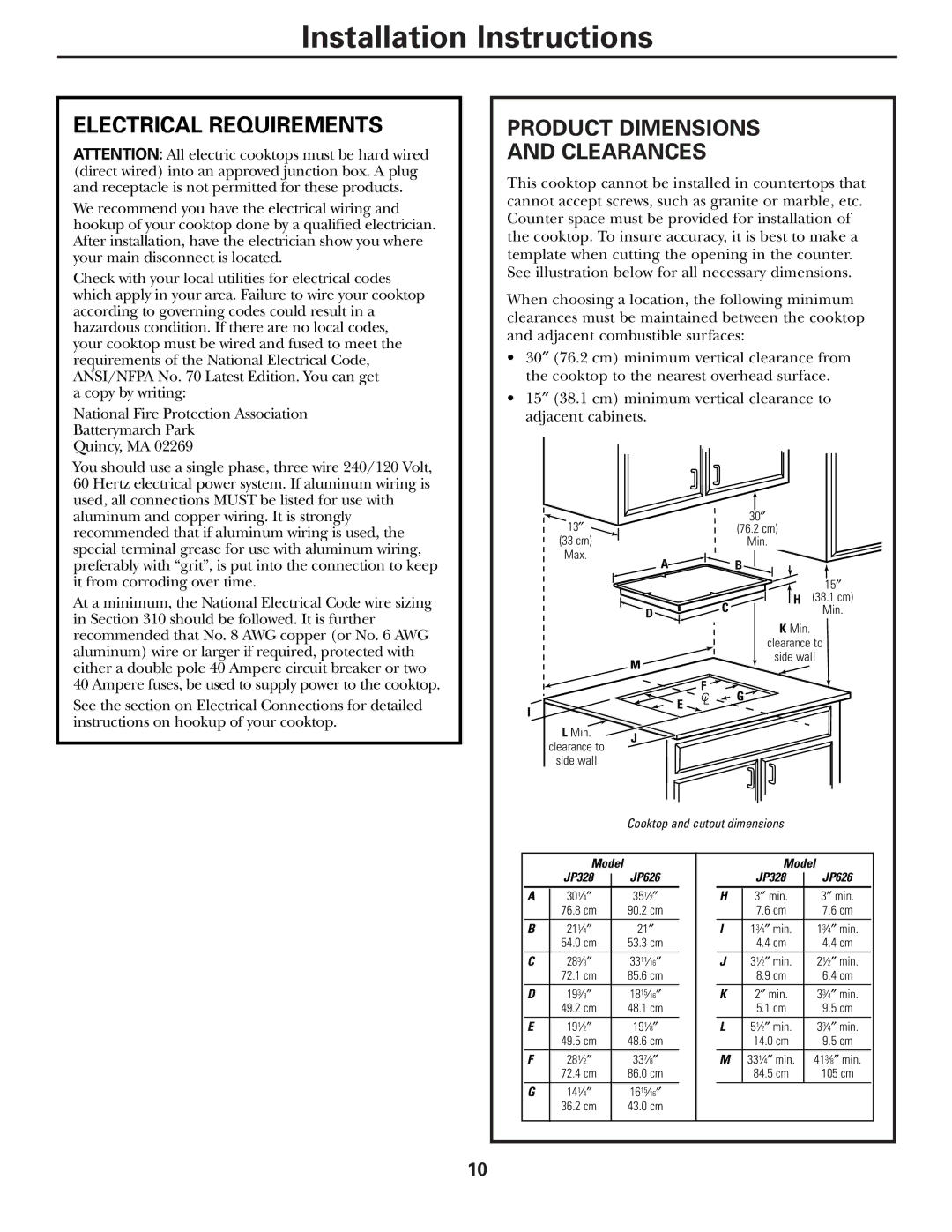
This cooktop cannot be installed in countertops that cannot accept screws, such as granite or marble, etc. Counter space must be provided for installation of the cooktop. To insure accuracy, it is best to make a template when cutting the opening in the counter. See illustration below for all necessary dimensions.
When choosing a location, the following minimum clearances must be maintained between the cooktop and adjacent combustible surfaces:
•30″ (76.2 cm) minimum vertical clearance from the cooktop to the nearest overhead surface.
•15″ (38.1 cm) minimum vertical clearance to adjacent cabinets.
|
|
|
|
|
|
|
|
|
|
|
|
|
|
|
|
|
|
|
|
|
|
|
|
|
| |||
|
|
| 13″ |
|
|
|
|
|
|
|
| 30″ |
|
|
|
|
| |||||||||||
|
|
|
|
|
|
|
|
|
| (76.2 cm) |
|
|
|
|
|
|
|
|
| |||||||||
|
|
| (33 cm) |
|
|
|
|
|
|
|
| Min. |
|
|
|
|
|
|
|
|
| |||||||
|
|
| Max. |
| A |
|
|
|
|
|
|
|
|
|
|
|
|
|
|
|
|
|
|
| ||||
|
|
|
|
|
|
|
| B |
|
|
|
|
|
|
|
|
|
|
| |||||||||
|
|
|
|
|
|
|
|
|
|
|
|
|
|
|
|
|
|
| ||||||||||
|
|
|
|
|
|
|
|
|
|
|
|
|
|
|
|
|
|
|
|
|
|
|
|
| ||||
|
|
|
|
|
|
|
|
|
|
|
|
|
|
|
|
|
|
| ||||||||||
|
|
|
|
|
|
|
|
|
|
|
|
|
|
|
|
|
|
|
|
|
|
|
| 15″ |
|
|
| |
|
|
|
|
|
|
|
|
|
|
|
|
|
| C |
|
|
|
|
| H |
| (38.1 cm) |
|
|
| |||
|
|
|
|
|
|
|
|
| D |
|
|
|
|
|
|
|
|
|
|
|
|
| Min. |
|
|
| ||
|
|
|
|
|
|
|
|
|
|
|
|
|
|
|
|
|
|
| K Min. |
|
|
|
|
| ||||
|
|
|
|
|
|
|
|
|
|
|
|
|
|
|
|
|
|
|
| |||||||||
|
|
|
|
|
|
|
|
|
|
|
|
|
|
|
|
| clearance to | |||||||||||
|
|
|
|
|
|
|
|
|
|
|
|
|
|
|
|
|
|
| side wall | |||||||||
|
|
|
|
|
|
|
| M |
|
|
|
|
|
|
|
|
|
| ||||||||||
|
|
|
|
|
|
|
|
|
|
|
|
|
|
|
|
|
|
|
|
|
|
|
|
|
|
|
| |
|
|
|
|
|
|
|
|
|
|
|
| F | G |
|
|
|
|
| ||||||||||
I |
|
|
|
|
|
|
|
| E |
|
|
|
|
| ||||||||||||||
|
|
|
|
|
|
|
|
|
|
|
|
|
|
|
|
|
|
|
|
|
| |||||||
|
|
|
|
|
|
|
|
|
|
|
|
|
|
|
|
|
|
|
|
|
|
|
|
|
|
| ||
|
|
| L Min. | J |
|
|
|
|
|
|
|
|
|
|
|
|
|
|
|
|
|
|
| |||||
|
| clearance to |
|
|
|
|
|
|
|
|
|
|
|
|
|
|
|
|
|
|
| |||||||
|
|
|
|
|
|
|
|
|
|
|
|
|
|
|
|
|
|
|
|
|
|
| ||||||
|
|
| side wall |
|
|
|
|
|
|
|
|
|
|
|
|
|
|
|
|
|
|
|
|
| ||||
|
|
|
|
|
|
|
|
|
|
|
|
|
|
|
|
|
|
|
|
|
|
|
|
|
|
| ||
|
|
|
|
|
|
|
|
|
|
|
|
|
|
|
|
|
|
|
|
|
|
| ||||||
|
|
|
|
|
|
|
| Cooktop and cutout dimensions |
|
|
|
|
| |||||||||||||||
|
|
|
|
|
|
|
|
|
|
|
|
|
|
|
|
|
|
|
|
|
|
|
| |||||
|
|
|
|
|
|
|
|
|
|
|
|
|
|
|
|
|
|
|
|
| ||||||||
|
|
| Model |
|
|
|
|
|
|
|
|
|
|
|
| Model |
| |||||||||||
|
|
| JP328 |
| JP626 |
|
|
|
|
|
| JP328 |
|
| JP626 |
| ||||||||||||
|
|
|
|
|
|
|
|
|
|
| ||||||||||||||||||
A |
| 301⁄4″ |
|
|
|
| 351⁄2″ |
|
|
|
| H |
| 3″ min. |
|
| 3″ min. |
|
| |||||||||
|
|
| 76.8 cm |
| 90.2 cm |
|
|
|
|
|
| 7.6 cm |
|
| 7.6 cm |
|
| |||||||||||
B |
| 211⁄4″ |
| 21″ |
|
|
|
| I |
| 13⁄4″ min. |
|
| 13⁄4″ min. |
| |||||||||||||
|
|
| 54.0 cm |
| 53.3 cm |
|
|
|
|
|
| 4.4 cm |
|
| 4.4 cm |
|
| |||||||||||
C |
| 283⁄8″ |
| 3311⁄16″ |
|
|
|
| J |
| 31⁄2″ min. |
|
| 21⁄2″ min. |
| |||||||||||||
|
|
| 72.1 cm |
| 85.6 cm |
|
|
|
|
|
| 8.9 cm |
|
| 6.4 cm |
|
| |||||||||||
D |
| 193⁄8″ |
| 1815⁄16″ |
|
|
|
| K |
| 2″ min. |
|
| 33⁄4″ min. |
| |||||||||||||
|
|
| 49.2 cm |
| 48.1 cm |
|
|
|
|
|
| 5.1 cm |
|
| 9.5 cm |
|
| |||||||||||
E |
| 191⁄2″ |
| 191⁄8″ |
|
|
|
| L |
| 51⁄2″ min. |
|
| 33⁄4″ min. |
| |||||||||||||
|
|
| 49.5 cm |
| 48.6 cm |
|
|
|
|
|
| 14.0 cm |
|
| 9.5 cm |
|
| |||||||||||
F |
| 281⁄2″ |
| 337⁄8″ |
|
|
|
| M |
| 331⁄4″ min. |
|
| 413⁄8″ min. |
| |||||||||||||
|
|
| 72.4 cm |
| 86.0 cm |
|
|
|
|
|
| 84.5 cm |
|
| 105 cm |
| ||||||||||||
G |
| 141⁄4″ |
| 1615⁄16″ |
|
|
|
|
|
|
|
|
|
|
|
|
|
|
|
|
|
|
| |||||
|
|
| 36.2 cm |
| 43.0 cm |
|
|
|
|
|
|
|
|
|
|
|
|
|
|
|
|
|
|
| ||||
|
|
|
|
|
|
|
|
|
|
|
|
|
|
|
|
|
|
|
|
|
|
|
|
|
|
|
|
|
10