INSTALLATION INSTRUCTIONS
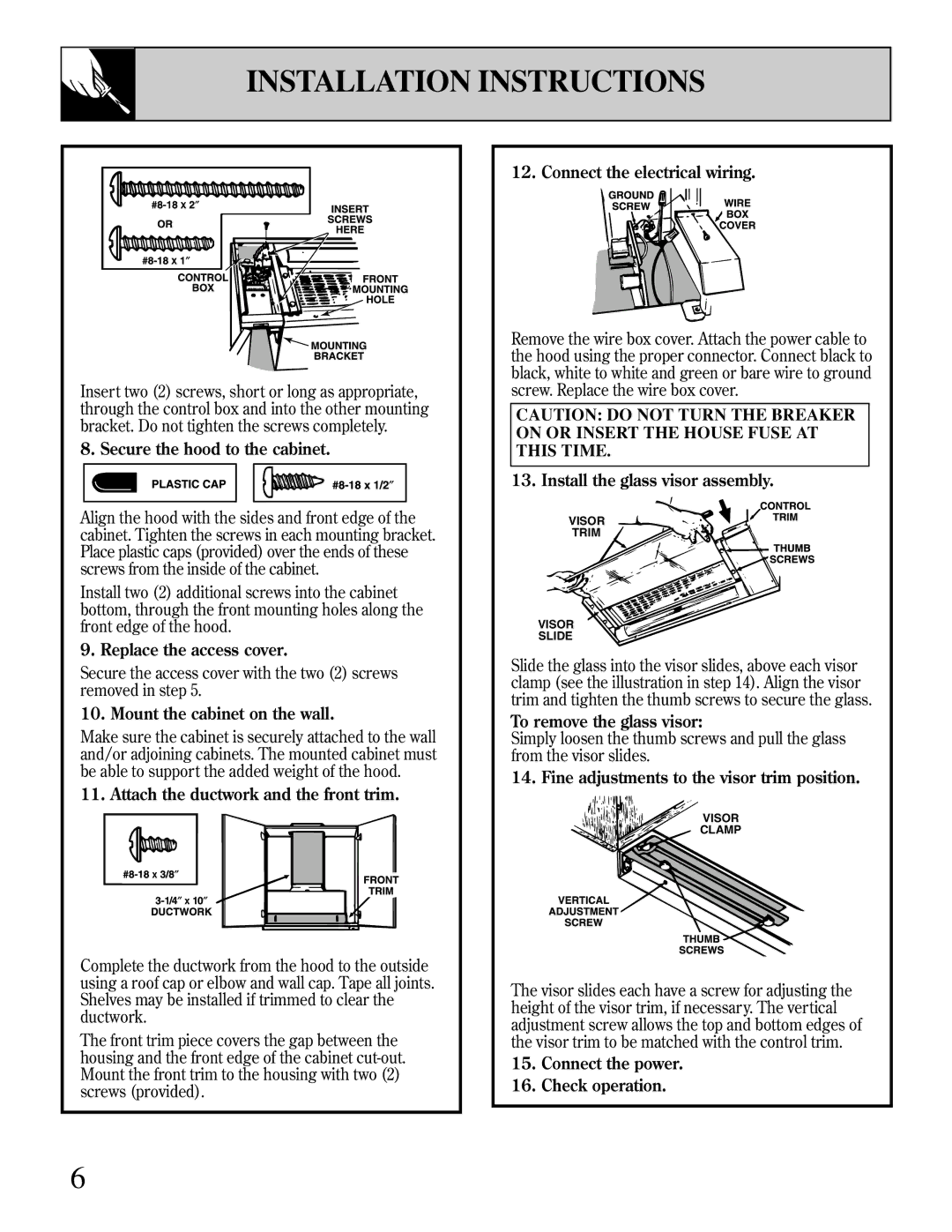
Insert two (2) screws, short or long as appropriate, through the control box and into the other mounting bracket. Do not tighten the screws completely.
8. Secure the hood to the cabinet.
Align the hood with the sides and front edge of the cabinet. Tighten the screws in each mounting bracket. Place plastic caps (provided) over the ends of these screws from the inside of the cabinet.
Install two (2) additional screws into the cabinet bottom, through the front mounting holes along the front edge of the hood.
9. Replace the access cover.
Secure the access cover with the two (2) screws removed in step 5.
10. Mount the cabinet on the wall.
Make sure the cabinet is securely attached to the wall and/or adjoining cabinets. The mounted cabinet must be able to support the added weight of the hood.
11. Attach the ductwork and the front trim.
Complete the ductwork from the hood to the outside using a roof cap or elbow and wall cap. Tape all joints. Shelves may be installed if trimmed to clear the ductwork.
The front trim piece covers the gap between the housing and the front edge of the cabinet
6
12. Connect the electrical wiring.
Remove the wire box cover. Attach the power cable to the hood using the proper connector. Connect black to black, white to white and green or bare wire to ground screw. Replace the wire box cover.
CAUTION: DO NOT TURN THE BREAKER ON OR INSERT THE HOUSE FUSE AT THIS TIME.
13. Install the glass visor assembly.
VISOR![]()
TRIM
VISOR ![]()
SLIDE
Slide the glass into the visor slides, above each visor clamp (see the illustration in step 14). Align the visor trim and tighten the thumb screws to secure the glass.
To remove the glass visor:
Simply loosen the thumb screws and pull the glass from the visor slides.
14. Fine adjustments to the visor trim position.
![]() VISOR
VISOR
![]() CLAMP
CLAMP
The visor slides each have a screw for adjusting the height of the visor trim, if necessary. The vertical adjustment screw allows the top and bottom edges of the visor trim to be matched with the control trim.