INSTALLATION INSTRUCTIONS
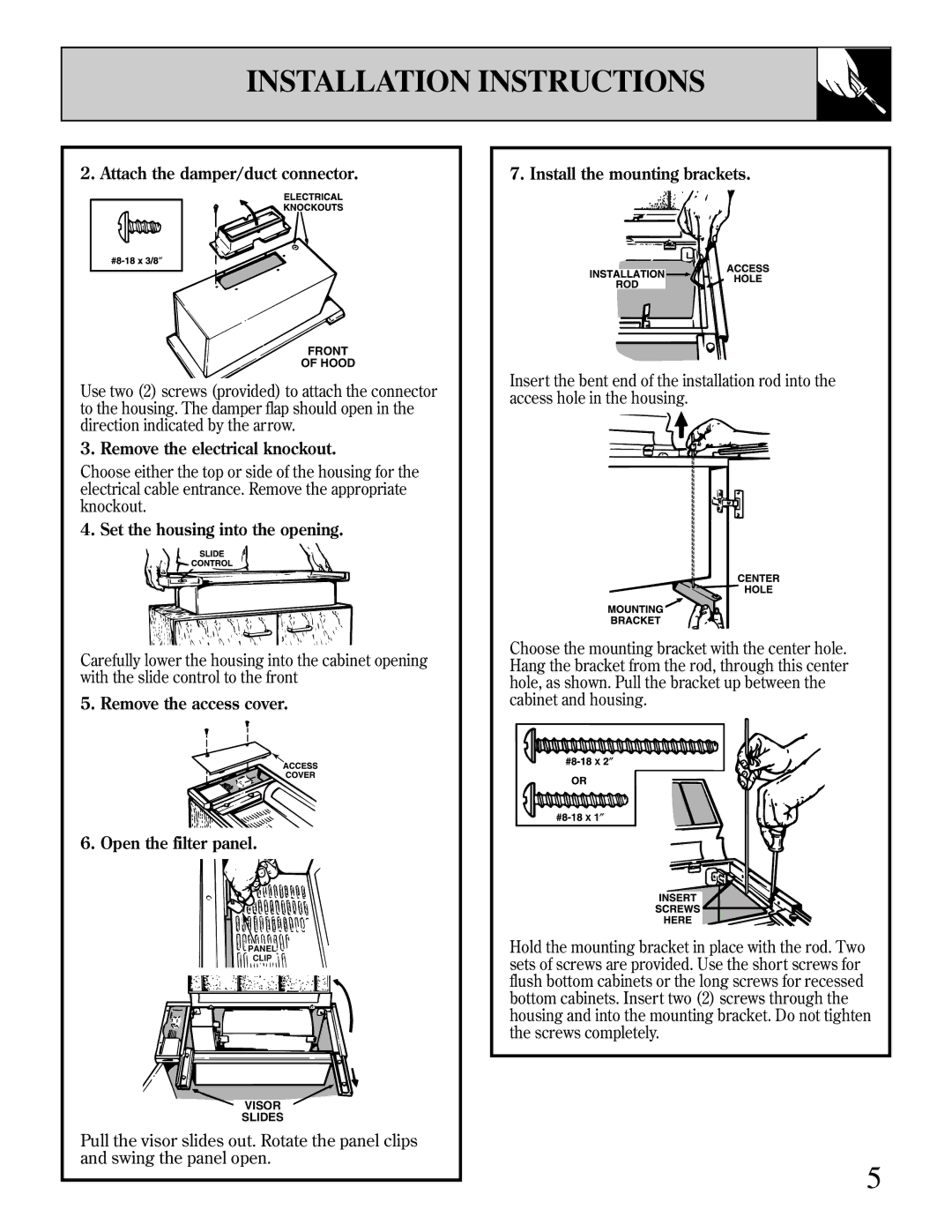
2. Attach the damper/duct connector.
FRONT
OF HOOD
Use two (2) screws (provided) to attach the connector to the housing. The damper flap should open in the direction indicated by the arrow.
3. Remove the electrical knockout.
Choose either the top or side of the housing for the electrical cable entrance. Remove the appropriate knockout.
4. Set the housing into the opening.
Carefully lower the housing into the cabinet opening with the slide control to the front
5.Remove the access cover.
6.Open the filter panel.
![]()
![]() PANEL
PANEL![]()
![]()
![]() CLIP
CLIP ![]()
![]()
![]() VISOR
VISOR![]()
![]()
SLIDES
Pull the visor slides out. Rotate the panel clips and swing the panel open.
7. Install the mounting brackets.
Insert the bent end of the installation rod into the access hole in the housing.
Choose the mounting bracket with the center hole. Hang the bracket from the rod, through this center hole, as shown. Pull the bracket up between the cabinet and housing.
Hold the mounting bracket in place with the rod. Two sets of screws are provided. Use the short screws for flush bottom cabinets or the long screws for recessed bottom cabinets. Insert two (2) screws through the housing and into the mounting bracket. Do not tighten the screws completely.
5