Installation Instructions
TOOLS AND MATERIALS YOU WILL NEED
Phillips head screwdriver
Adjustable pliers (adjust leveling legs)
Carpenter’s level
Flat or straight blade screwdriver (may be needed for cord strain relief)
Duct tape
Rigid or
Vent hood
1/4″ nut driver (remove terminal block access cover and install cord) (ELECTRIC DRYER)
Pipe thread sealer (GAS DRYER)
Flexible stainless steel or
(GAS DRYER)
PREPARING THE INSTALLATION SITE AND UNPACKING YOUR DRYER
1.Prepare the area and exhaust for installation of the new dryer.
2.Check to be sure that the existing external exhaust is clean and that it meets attached installation specifications.
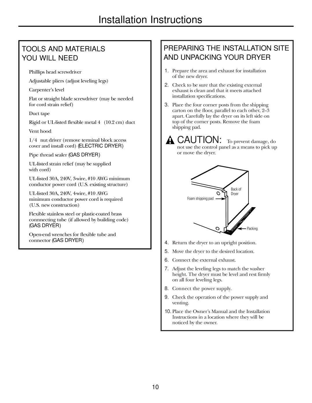
3.Place the four corner posts from the shipping carton on the floor, parallel to each other,
![]() CAUTION: To prevent damage, do not use the control panel as a means to pick up or move the dryer.
CAUTION: To prevent damage, do not use the control panel as a means to pick up or move the dryer.
Back of
Dryer
Foam shipping pad
![]()
![]() Packing
Packing
4.Return the dryer to an upright position.
5.Move the dryer to the desired location.
6.Connect the external exhaust.
7.Adjust the leveling legs to match the washer height. The dryer must be level and rest firmly on all four leveling legs.
8.Connect the power supply.
9.Check the operation of the power supply and venting.
10.Place the Owner’s Manual and the Installation Instructions in a location where they will be noticed by the owner.
10