zbd0710NSS/ZBD0700NII
GE Monogram® Fully Integrated
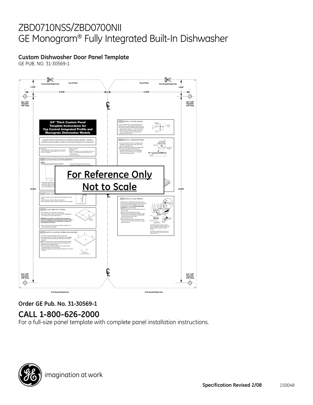
Custom Dishwasher Door Panel Template
ge pub. no. 31-30569-1
| Trim Around Dotted Line | Top of Panel | Top of Panel | Trim Around Dotted Line |
|
|
|
|
| ||
|
| ||||
|
|
| |||
Drill 3/32" |
|
|
| Drill 3/32" | |
Pilot Hole |
|
|
| Pilot Hole | |
3/32" Deep |
|
|
| 3/32" Deep | |
3/4" Thick Custom Panel | STEP 5 INSTALL CUSTOM HANDLE | Be Countersunk |
| |||||
|
|
|
|
|
|
| Screws Must |
|
Template Instructions for | A custom handle must be installed onto the panel | Into Panel | ||||||
|
|
| of Panel | |||||
|
|
|
|
| before the panel is secured to the dishwasher door. |
| From Top | |
Top Control Integrated Profile and | • The handle should be installed so that it aligns with | Custom |
| |||||
top of the panel. Secure the handle in the same |
| |||||||
Monogram Dishwasher Models | adjacent drawer handles, or |
| Handle | |||||
countersunk into the panel. |
|
| ||||||
|
|
|
|
| manner as cabinet handles. Screws must be | Door Panel |
| |
The custom panel should be sized to your installation situation. See Step 1. For easier | STEP 6 INSTALL ASSEMBLED PANEL |
| Custom | |||||
installation the custom panel and custom handle should be attached before installing the |
|
|
| Panel | ||||
dishwasher. Use this template to locate mounting screws and spacers on the custom panel. | • Secure the panel to the door by inserting the top |
|
| |||||
|
|
|
|
|
|
| ||
|
|
|
|
| and bottom mounting screws with spacers into | Dishwasher |
| |
|
|
|
|
| the matching keyhole slots. | Door |
| |
|
|
|
|
| • Make sure all 4 spacers engage the keyhole slots. |
| Shoulder Washers | |
IMPORTANT | PARTS INCLUDED: |
| • Press the panel against the door and push |
| Engage Keyhole | |||
|
| Slots | ||||||
• A custom handle must be installed onto the custom | (4) Spacers |
|
|
| downward until the spacers are fully engaged |
|
| |
panel. Install the custom handle | (4) #8 x 5/8" Phillips truss head stainless steel screws | into the key hole slots. The panel should align |
|
| ||||
the top of the panel. | (3) #8 x | evenly with the top and sides. |
|
| ||||
| wood screws |
|
|
|
| |||
| (2) Heavy duty springs |
|
|
|
|
| ||
STEP 1 CUSTOM PANEL SIZE REQUIREMENTS |
|
|
|
|
|
|
| |
HEIGHT |
|
|
|
|
|
|
|
|
Panel height must be between | • The top of the custom panel must be flush |
|
|
|
| |||
| with the top of the door. The 1/2" minimum gap |
|
|
|
| |||
| between the top of the door and the bottom of the |
|
|
|
| |||
| countert | p must be maintained. |
|
|
|
| ||
|
|
| for ClearanceReference |
|
| |||
|
|
| Countertop | • Stand the dishwasher upright. |
|
| ||
|
|
|
| • Open dishwash | door and drive the supplied |
|
| |
|
|
|
|
|
| |||
|
|
|
| 1/2" min. | #8 x | ad screws. Drive one screw at |
|
|
|
|
|
| the top and one on each side as shown, through |
|
| ||
|
|
| Minimum 1/2" Gap | the inner door and into the custom panel. |
|
| ||
ForWIDTH |
|
| screws. Excessive |
|
| |||
| WARNING: Do not overtightenOnly |
| ||||||
| Panel width must be | Not to Scale |
|
| ||||
• If the panel height is more than | • If the panel width is less than |
|
|
|
| |||
prevent the door from swinging open. | cover the dishwasher frame. |
|
|
|
| |||
• If the panel height is less than | IMPORTANT: To ensure optimum door balance |
|
| Custom |
| |||
cover the dishwasher door frame. | performance, the custom panel must not weigh m re |
|
| Panel |
| |||
than 14 lbs. |
|
|
|
|
| |||
STEP 2 DRAW CENTERLINE |
|
|
|
|
|
|
|
|
• Place the custom panel on a flat surface with appearance side |
|
|
|
|
|
|
| |
down. |
|
|
|
| STEP 7 INSTALL DOOR SPRINGS |
|
| |
• Locate the vertical center of the panel at the top. |
|
|
|
|
|
|
|
|
• Use a carpenters square to draw a centerline from top to bottom. |
|
|
| The dishwasher is shipped from the factory with a |
| Use This | ||
|
|
|
|
|
| |||
|
|
|
|
| temporary set of balance springs. Use the heavy duty |
| Mounting | |
|
|
|
|
| springs provided and the adjustment holes in the |
| Hole | |
|
|
|
|
| cable to balance the door after the custom panel |
|
| |
|
|
|
|
| is installed onto the dishwasher. |
|
| |
STEP 3 ALIGN TEMPLATE TO PANEL |
|
|
|
| • With the dishwasher on the wood skid, close and |
|
| |
|
|
|
|
| latch the door. |
|
| |
• Trim template on the dotted line along all sides. |
|
|
|
| • Remove and discard both door springs. |
|
| |
• Place the template on the panel aligned with the top edge and |
|
|
| • Attach the new heavy duty door springs. Engage |
|
| ||
the centerline. Use tape to hold in place. |
|
|
|
| the end with the short hook into the support leg | Pulley |
| |
|
|
|
| and the long hook into the cable. |
| |||
|
|
|
|
|
|
| ||
IMPORTANT: If the template is not aligned with the top edge of the |
|
|
| • Open and close the door. |
| Decrease | ||
panel, the 1/2" minimum gap will not be maintained. This 1/2" minimum |
|
| Mark Center | • If the door drops open when released, increase |
| Tension | ||
|
| Screw Holes | spring tension. If the door closes when released, | Shoulder |
| |||
gap must be maintained to prevent condensation and damage to the |
|
|
| Increase | ||||
control panel from screw heads. |
|
|
|
| decrease tension. | Correct Spring | Tension | |
|
|
|
| Cable Routing |
| |||
• Use an awl to mark the screw hole locations indicated on the |
|
|
|
|
| TIP: If the door does not open easily or falls too | ||
|
|
|
|
| quickly, check spring cable routing. The cable is held | |||
template. Remove the template. |
|
|
|
|
|
| in place by “shoulders” on the pulley. Check to be | |
|
|
|
|
|
|
| sure the cable has not slipped over the pulley | |
|
|
|
|
|
|
| shoulders. |
|
STEP 4 INSTALL MOUNTING SCREWS AND SPACERS |
|
|
|
| IMPORTANT: Adjust both balance springs to the | |||
|
|
|
| same amount of tension to prevent excessive door | ||||
|
|
|
|
|
|
| twisting during use. |
|
If the panel is less than 3/4" thick, shorter screws must |
|
|
|
|
|
|
| |
be used. Use #8 x 1/2" screws for 1/2" thick panels (not supplied). |
|
|
|
|
|
|
| |
• Use a 3/32" drill bit to drill pilot holes 3/32" deep in the marked |
|
|
|
|
|
|
| |
locations. |
|
|
|
|
|
|
|
|
Note: The custom panel is secured to the dishwasher door with |
|
|
|
|
|
|
| |
the spacers and screws provided. The spacer will slip into the |
|
|
|
|
|
|
| |
keyhole slots on the dishwasher door. |
|
|
|
|
|
|
|
|
• Drive the supplied #8 x 5/8" Phillips truss head steel screws |
|
|
|
|
|
|
| |
through the spacer and into the panel. |
|
|
|
|
|
|
|
|
• Install remaining spacers and screws as indicated in the marked |
|
| Screw |
|
|
|
| |
locations. |
|
| Spacer |
|
|
|
| |
Drill 3/32"
Pilot Hole
3/32" Deep
Drill 3/32"
Pilot Hole
3/32" Deep
Trim Around Dotted Line | Trim Around Dotted Line |
Order GE Pub. No. 31-30569-1
CALL 1-800-626-2000
For a
Specification Revised 2/08 | 150048 |