Section 1 — General Information
Guardian
1.6MAIN CIRCUIT BREAKER
The generator’s main circuit breaker is included with the unit as shipped from the factory. The breaker for each unit is described as follows:
| Model Number | Circuit Breaker Rating |
|
| 0043736 |
| |
| 0046265 |
| |
|
|
|
|
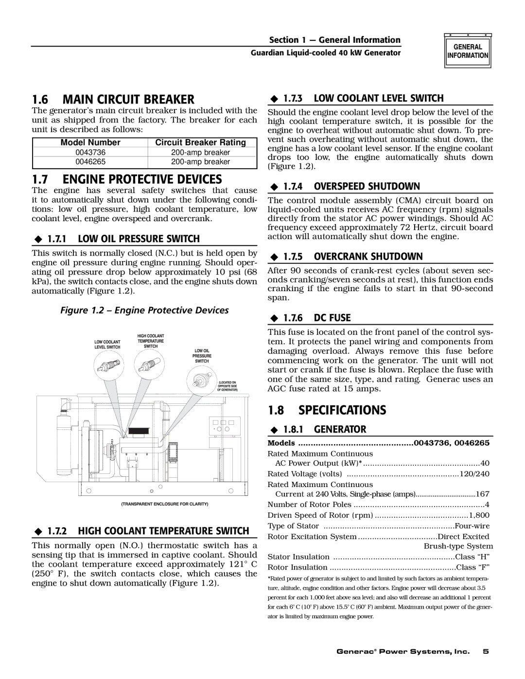
1.7.3 LOW COOLANT LEVEL SWITCH
Should the engine coolant level drop below the level of the high coolant temperature switch, it is possible for the engine to overheat without automatic shut down. To pre- vent such overheating without automatic shut down, the engine has a low coolant level sensor. If the engine coolant drops too low, the engine automatically shuts down (Figure 1.2).
1.7ENGINE PROTECTIVE DEVICES
The engine has several safety switches that cause it to automatically shut down under the following condi- tions: low oil pressure, high coolant temperature, low coolant level, engine overspeed and overcrank.
1.7.1 LOW OIL PRESSURE SWITCH
This switch is normally closed (N.C.) but is held open by engine oil pressure during engine running. Should oper- ating oil pressure drop below approximately 10 psi (68 kPa), the switch contacts close, and the engine shuts down automatically (Figure 1.2).
1.7.4 OVERSPEED SHUTDOWN
The control module assembly (CMA) circuit board on
1.7.5 OVERCRANK SHUTDOWN
After 90 seconds of
Figure 1.2 – Engine Protective Devices | 1.7.6 DC FUSE |
|
1.7.2 HIGH COOLANT TEMPERATURE SWITCH
This normally open (N.O.) thermostatic switch has a sensing tip that is immersed in captive coolant. Should the coolant temperature exceed approximately 121° C (250° F), the switch contacts close, which causes the engine to shut down automatically (Figure 1.2).
This fuse is located on the front panel of the control sys- tem. It protects the panel wiring and components from damaging overload. Always remove this fuse before commencing work on the generator. The unit will not start or crank if the fuse is blown. Replace the fuse with one of the same size, type, and rating. Generac uses an AGC fuse rated at 15 amps.
1.8SPECIFICATIONS
◆ 1.8.1 GENERATOR |
|
|
Models | 0043736, 0046265 | |
Rated Maximum Continuous |
|
|
AC Power Output (kW)* | 40 | |
Rated Voltage (volts) | 120/240 | |
Rated Maximum Continuous |
|
|
Current at 240 Volts, | 167 | |
Number of Rotor Poles | 4 | |
Driven Speed of Rotor (rpm) | 1,800 | |
Type of Stator | ||
Rotor Excitation System | Direct Excited | |
|
| |
Stator Insulation | Class “H” | |
Rotor Insulation | Class “F” | |
*Rated power of generator is subject to and limited by such factors as ambient tempera- ture, altitude, engine condition and other factors. Engine power will decrease about 3.5 percent for each 1,000 feet above sea level; and also will decrease an additional 1 percent for each 6° C (10° F) above 15.5° C (60° F) ambient. Maximum output power of the gener- ator is limited by maximum engine power.
Generac® Power Systems, Inc. 5