Section 1 — General Information
Guardian
1.1UNPACKING/INSPECTION
After unpacking, carefully inspect the contents for dam- age.
•This standby generator set has been factory installed in an
If this generator is used to power electrical load circuits normally powered by a utility power source, code requires to install a transfer switch. The transfer switch must effectively isolate the electrical system from the utility distribution sys- tem when the generator is operating (NEC 701). Failure to isolate an electrical system by such means will result in damage to the generator and also may result in injury or death to utility power workers due to backfeed of electrical energy.
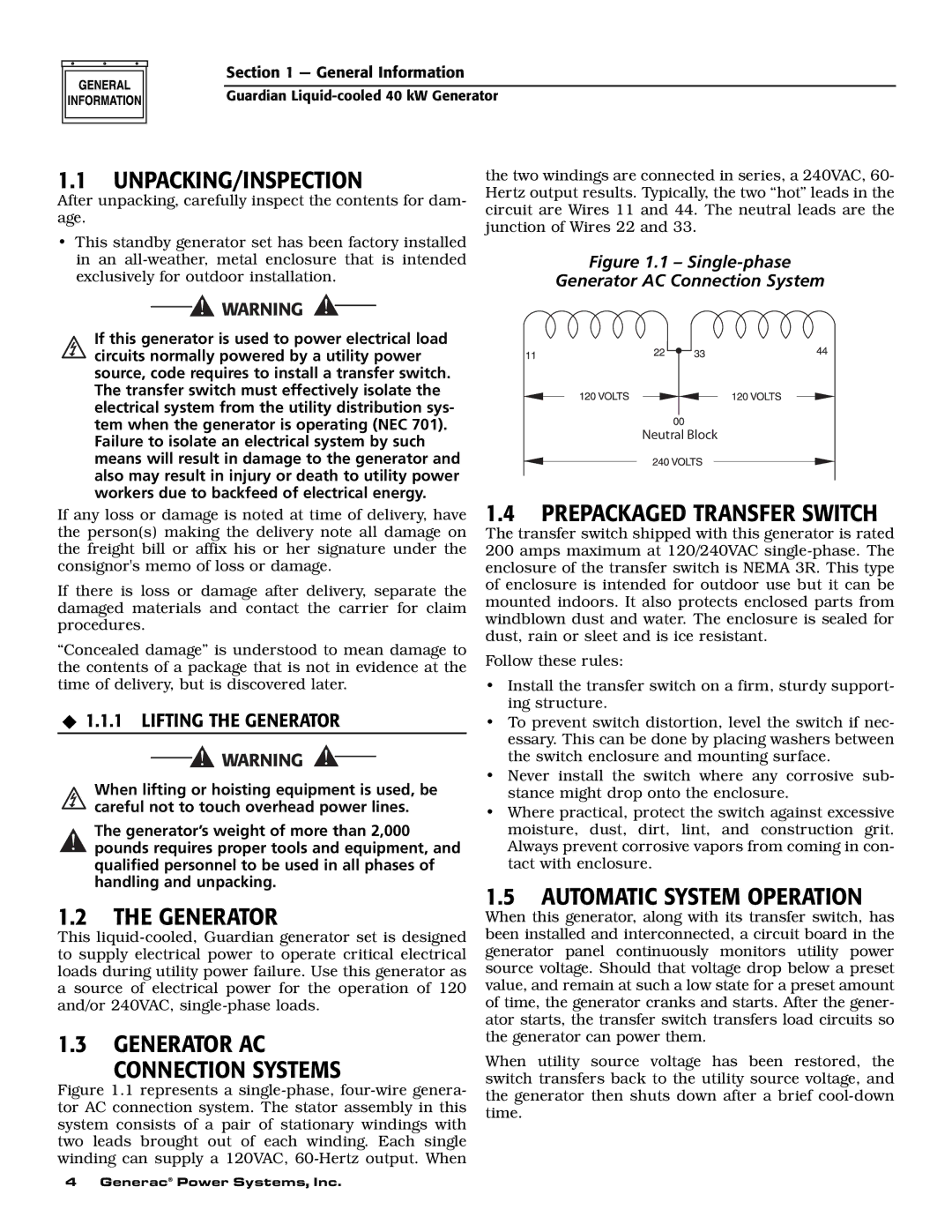
the two windings are connected in series, a 240VAC, 60- Hertz output results. Typically, the two “hot” leads in the circuit are Wires 11 and 44. The neutral leads are the junction of Wires 22 and 33.
Figure 1.1 – Single-phase
Generator AC Connection System
Neutral Block
If any loss or damage is noted at time of delivery, have the person(s) making the delivery note all damage on the freight bill or affix his or her signature under the consignor's memo of loss or damage.
If there is loss or damage after delivery, separate the damaged materials and contact the carrier for claim procedures.
“Concealed damage” is understood to mean damage to the contents of a package that is not in evidence at the time of delivery, but is discovered later.
1.1.1 LIFTING THE GENERATOR
When lifting or hoisting equipment is used, be careful not to touch overhead power lines.
The generator’s weight of more than 2,000
!pounds requires proper tools and equipment, and qualified personnel to be used in all phases of handling and unpacking.
1.2THE GENERATOR
This
1.3GENERATOR AC
CONNECTION SYSTEMS
Figure 1.1 represents a single-phase, four-wire genera- tor AC connection system. The stator assembly in this system consists of a pair of stationary windings with two leads brought out of each winding. Each single winding can supply a 120VAC, 60-Hertz output. When
1.4PREPACKAGED TRANSFER SWITCH
The transfer switch shipped with this generator is rated 200 amps maximum at 120/240VAC
Follow these rules:
•Install the transfer switch on a firm, sturdy support- ing structure.
•To prevent switch distortion, level the switch if nec- essary. This can be done by placing washers between the switch enclosure and mounting surface.
•Never install the switch where any corrosive sub- stance might drop onto the enclosure.
•Where practical, protect the switch against excessive moisture, dust, dirt, lint, and construction grit. Always prevent corrosive vapors from coming in con- tact with enclosure.
1.5AUTOMATIC SYSTEM OPERATION
When this generator, along with its transfer switch, has been installed and interconnected, a circuit board in the generator panel continuously monitors utility power source voltage. Should that voltage drop below a preset value, and remain at such a low state for a preset amount of time, the generator cranks and starts. After the gener- ator starts, the transfer switch transfers load circuits so the generator can power them.
When utility source voltage has been restored, the switch transfers back to the utility source voltage, and the generator then shuts down after a brief
4 Generac® Power Systems, Inc.
