Manuals
/
Generac
/
Lawn and Garden
/
Portable Generator
Generac
00941-3 2.4PROPANE GAS FUEL SYSTEM, Compensating For Restrictions, Inverter Location
Models:
00941-3
1
27
52
52
Download
52 pages
19.55 Kb
24
25
26
27
28
29
30
31
Troubleshooting
Specification
Install
Wiring
Warranty
Maintenance
2.8OPTIONAL ACCESSORIES
Battery
Checklist
3.5ENGINE AIR CLEANER
Page 27
Image 27
Page 26
Page 28
Page 27
Image 27
Page 26
Page 28
Contents
This manual should remain with the unit
Air-cooledRecreational Vehicle Generator
Model No 00941-3 IMPACT-36plus II with Inverter
HOW TO OBTAIN SERVICE
AUTHORIZED SERVICE DEALER LOCATION
CONTENTS
OPERATION AND MAINTENANCE
Table of Contents
Part II - Installation Instructions
IMPACT-36plus II Recreational Vehicle Generator
GENERAL HAZARDS
ELECTRICAL HAZARDS
FIRE HAZARDS
EXPLOSION HAZARDS
REFERENCE NUMBER IDENTIFICATION
1.1.1 IMPACT-36LPGPLUS II FEATURES
1.1GENERATOR IDENTIFICATION
2 11 3 12 4 16
1.1.2 INVERTER FEATURES PART NO. 0D4885
1.4GENERATOR CONTROL PANEL
1.3SAFETY
1.4.2 START/STOP SWITCH
1.2GENERATOR APPLICABILITY
2.1BEFORE STARTING THE ENGINE
1.5ENGINE PROTECTIVE DEVICES
2.1.5 ENGINE EXHAUST GAS
2.2STARTING THE GENERATOR
2.3STOPPING THE GENERATOR
2.1.4 COOLING AND VENTILATING AIR
2.5ATTENTION REQUIRED AFTER SUBMERSION
2.7OPERATING PRECAUTIONS
2.10 LP GENERATOR SPECIFICATIONS
2.11 ENGINE SPECIFICATIONS
3.4CHANGE OIL FILTER
3.1MAINTENANCE
3.2CHECKING ENGINE OIL LEVEL
3.3CHANGE ENGINE OIL
3.7ENGINE SPARK PLUG
3.5ENGINE AIR CLEANER
3.6CLEAN AIR INTAKE SCREEN
3.9 CLEANING THE GENERATOR
3.13 ADJUSTING VALVE CLEARANCE
3.11 SERVICE AND ADJUSTMENTS
3.10 BATTERY
3.12 ADJUSTING THE CARBURETOR
Figure 3.9 - Tightening Jam Nut
3.16 OUT OF SERVICE PROTECTION
3.17 RETURN UNIT TO SERVICE AFTER STORAGE
3.15 EXERCISING THE GENERATOR
14 Generac Power Systems, Inc
ONLY QUALIFIED ELECTRICIANS OR CONTRACTORS
INSTALLATION INSTRUCTIONS
SHOULD ATTEMPT INSTALLATION
PART
NOTICE TO INSTALLER
FIRE HAZARDS
1.4EQUIPMENT DESCRIPTION
1.2SAFETY
1.1PURPOSE AND SCOPE OF THE MANUAL
1.3STANDARDS BOOKLETS
2.1.3 SUSPENDED MOUNTING
2.1LOCATION AND SUPPORT
2.1.1 GENERATOR LOCATION
2.1.2 GENERATOR SUPPORT
Figure 2.4 - Types of Lock Seams
2.2GENERATOR COMPARTMENTS
2.1.4 GENERATOR RESTRAINT
Figure 2.3 - Typical Generator Restraint
Figure 2.6 - Typical Compartment Construction
2.2.1 COMPARTMENT SIZE
2.2.2 COMPARTMENT CONSTRUCTION
Figure 2.5 - Provide Clearance Around Generator
2.2.3 SOUND INSULATING MATERIALS
2.2.4 COMPARTMENT FLOOR CUTOUTS
Figure 2.7 - Compartment Floor Cutout 0A6203-A
Figure 2.8 - Typical Noise Abatement Compartment
2.3COOLING AND VENTILATING AIR
2.2.5 ACOUSTICS
2.3.1 GENERATOR AIR FLOW
Figure 2.10 - Air Inlet in Compartment Door
2.3.2 COOLING AIR INLET OPENINGS
Figure 2.12 - Air Inlet Using Ductwork
Figure 2.11 - Suspended Mount Inlet Door
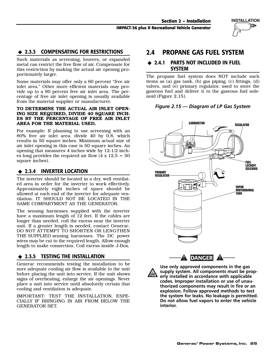
2.4.1 PARTS NOT INCLUDED IN FUEL SYSTEM
2.3.5 TESTING THE INSTALLATION
2.4PROPANE GAS FUEL SYSTEM
2.3.3 COMPENSATING FOR RESTRICTIONS
2.4.5 GASEOUS CARBURETION
2.4.2 SOME IMPORTANT CONSIDERATIONS
2.4.3 VAPOR WITHDRAWAL
2.4.4 PRIMARY REGULATOR
2.4.8 LEAKAGE TESTS
2.5EXHAUST SYSTEM
2.4.6 FUEL SUPPLY LINES
2.4.7 EXCESS FLOW VALVE
Figure 2.17 - Exhaust System
2.5.3 EXHAUST SYSTEM SAFETY
2.6ELECTRICAL CONNECTIONS
2.5.2 TYPE OF EXHAUST SYSTEM
2.6.2 GENERATOR AC CONNECTION SYSTEM
2.6.1 WIRING
2.6.3 ISOLATING DIFFERENT POWER SOURCES
2.6.4 POWER SUPPLY CORD
30 Generac Power Systems, Inc
Figure 2.20 - Transfer Switch Isolation Method
INVERTER POWER SUPPLY CORD POWER CORD FOR
DOCKSIDE POWER
2.6.6 SENSING HARNESS
2.7BATTERY INSTALLATION
2.7.1 RECOMMENDED BATTERY
2.7.2 BATTERY CABLES
2.8.1 REMOTE PLUG-INRECEPTACLE
2.8OPTIONAL ACCESSORIES
2.7.3 BATTERY CABLE CONNECTIONS
2.7.4 BATTERY COMPARTMENT
3.3INITIAL START
3.1POST INSTALLATION TESTS
3.4TESTING UNDER LOAD
3.2BEFORE INITIAL START UP
POST INSTALLATION TESTS
3.5INSTALLATION CHECKLIST
BATTERY INSTALLATION
OPTIONAL ACCESSORIES
CORRECTION
4.1TROUBLESHOOTING GUIDE
PROBLEM
CAUSE
36 Generac Power Systems, Inc
Section 6 - Electrical Data
38 Generac Power Systems, Inc
Section 6 - Electrical Data
40 Generac Power Systems, Inc
Section 7 - Exploded Views and Parts Lists
Control Panel - Drawing No. 0E7560
DESCRIPTION
42 Generac Power Systems, Inc
Section 7 - Exploded Views and Parts Lists
GN 220 RV Long Block - Drawing No. 0A6202-G
44 Generac Power Systems, Inc
078621
46 Generac Power Systems, Inc
Section 7 - Exploded Views and Parts Lists
ATTENTION WARRANTY DEPARTMENT
YOUR WARRANTY RIGHTS AND OBLIGATIONS
PURCHASER’S/OWNER’S WARRANTY RESPONSIBILITIES
Section 8 - Warranty
EMISSION RELATED PARTS INCLUDE THE FOLLOWING
EMISSION CONTROL SYSTEM WARRANTY
FOR GUARDIAN RECREATIONAL VEHICLE GENERATORS
GENERAC POWER SYSTEMS’ THREE-YEARLIMITED WARRANTY
WARRANTY SCHEDULE - COMMERCIAL APPLICATIONS
GENERAC POWER SYSTEMS, INC
Top
Page
Image
Contents