Section 1 – General Information
1.2GENERATOR APPLICABILITY
These generators have been designed and manufac- tured for supplying electrical power for recreational vehicles. Do not modify the generator or use it for any application other than for what it was designed. If there are questions pertaining to its application, write or call the factory. Do not use the unit until advised by a competent authority.
![]()
![]() DANGER
DANGER
For fire safety, the generator must have been properly installed in compliance with (1) ANSI
This generator has been designed to work with an inverter (P/N 0D4885). The inverter changes the volt- age from the generator from a DC to an AC voltage. This generator will not operate properly without the inverter box connected. All repairs of the inverter must be handled by an authorized service dealer (see Page 12 in “Maintenance”).
Use this generator to supply electrical power for operating 120 volts, single phase, 60 Hertz, electrical loads. These loads can require up to 3400 watts (3.4 kW) for the
Do not overload the generator. Some installa-
!tions may require that electrical loads be alternated to avoid overloading. Applying excessively high electrical loads may damage the generator and may shorten its life. Add up the rated watts of all electrical lighting, appliance, tool and motor loads the generator will power at one time. This total should not be greater than the wattage capacity of the generator. If an electrical device nameplate gives only volts and amps, multiply volts times amps to obtain watts (volts x amps = watts). Some electric motors require more amps of current for starting than for continu- ous operation.
1.3SAFETY
Before using the generator set, carefully read GEN- ERAL SAFETY RULES inside the cover. Comply with these RULES to prevent accidents and damage to equipment and/or property. Generac suggests copy- ing and posting the GENERAL SAFETY RULES in potential hazard areas of the recreational vehicle. Safety should be stressed to all operators of this equipment.
1.4GENERATOR CONTROL PANEL
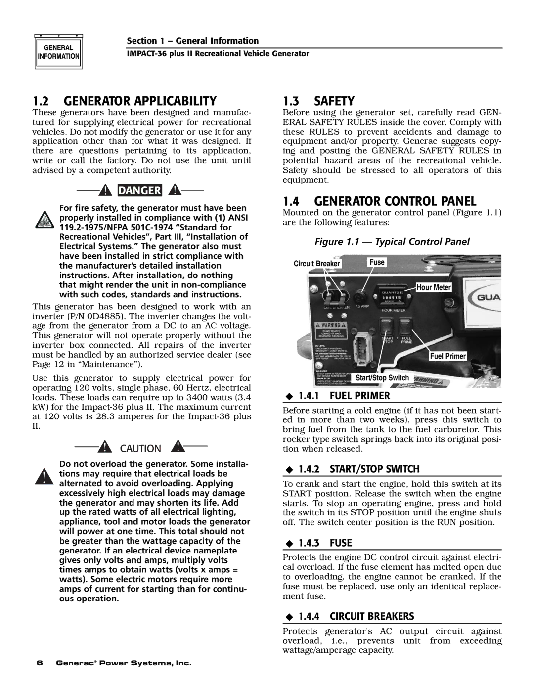
Mounted on the generator control panel (Figure 1.1) are the following features:
Figure 1.1 — Typical Control Panel
Circuit Breaker |
| Fuse |
|
|
|
![]() Hour Meter
Hour Meter
Fuel Primer
Start/Stop Switch
◆1.4.1 FUEL PRIMER
Before starting a cold engine (if it has not been start- ed in more than two weeks), press this switch to bring fuel from the tank to the fuel carburetor. This rocker type switch springs back into its original posi- tion when released.
◆1.4.2 START/STOP SWITCH
To crank and start the engine, hold this switch at its START position. Release the switch when the engine starts. To stop an operating engine, press and hold the switch in its STOP position until the engine shuts off. The switch center position is the RUN position.
◆1.4.3 FUSE
Protects the engine DC control circuit against electri- cal overload. If the fuse element has melted open due to overloading, the engine cannot be cranked. If the fuse must be replaced, use only an identical replace- ment fuse.
◆1.4.4 CIRCUIT BREAKERS
Protects generator's AC output circuit against overload, i.e., prevents unit from exceeding wattage/amperage capacity.
6 Generac® Power Systems, Inc.