Section 3 - Operation
Guardian
AUTO — The control board will monitor the
NOTE:
If the generator is installed in conjunction with a standard GTS type transfer switch, refer to the applicable transfer switch manual for exact oper- ating parameters and timing sequences.
3.2.2 FAULT INDICATOR LED
This LED goes ON when one or more of the following engine faults occurs and when engine shuts down.
•Low Oil Pressure
•Overcrank
•Low Battery
•Overspeed/RPM Sensor Loss
•High Coolant Temperature/Low Coolant Level
See Section 1.7 for further explanation of engine pro- tection functions.
3.2CONTROL CONSOLE
COMPONENTS
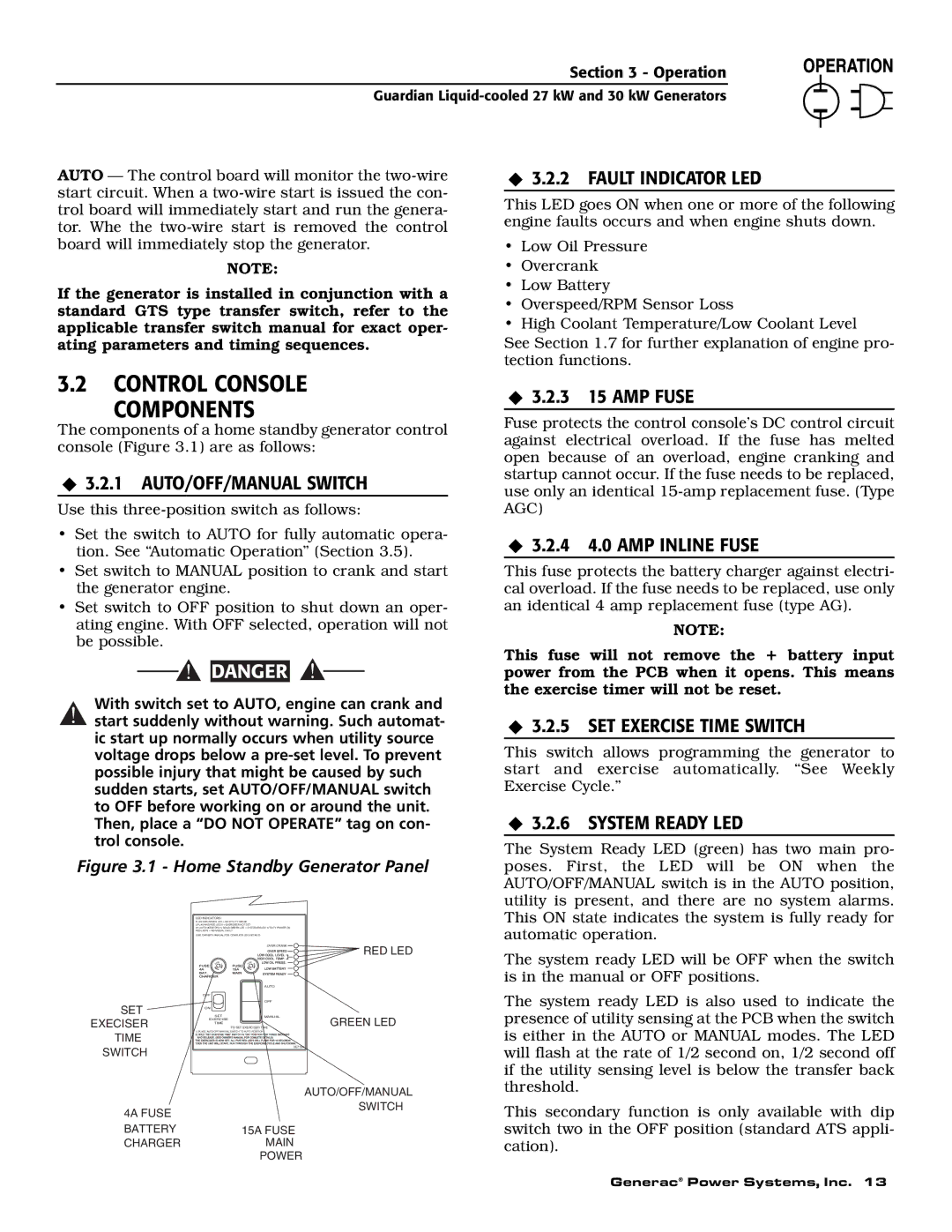
The components of a home standby generator control console (Figure 3.1) are as follows:
3.2.1 AUTO/OFF/MANUAL SWITCH
Use this
•Set the switch to AUTO for fully automatic opera- tion. See “Automatic Operation” (Section 3.5).
•Set switch to MANUAL position to crank and start the generator engine.
•Set switch to OFF position to shut down an oper- ating engine. With OFF selected, operation will not be possible.
![]()
![]() DANGER
DANGER
With switch set to AUTO, engine can crank and
!start suddenly without warning. Such automat- ic start up normally occurs when utility source voltage drops below a
Figure 3.1 - Home Standby Generator Panel
3.2.3 15 AMP FUSE
Fuse protects the control console’s DC control circuit against electrical overload. If the fuse has melted open because of an overload, engine cranking and startup cannot occur. If the fuse needs to be replaced, use only an identical
3.2.4 4.0 AMP INLINE FUSE
This fuse protects the battery charger against electri- cal overload. If the fuse needs to be replaced, use only an identical 4 amp replacement fuse (type AG).
NOTE:
This fuse will not remove the + battery input power from the PCB when it opens. This means the exercise timer will not be reset.
3.2.5 SET EXERCISE TIME SWITCH
This switch allows programming the generator to start and exercise automatically. “See Weekly Exercise Cycle.”
3.2.6 SYSTEM READY LED
The System Ready LED (green) has two main pro- poses. First, the LED will be ON when the AUTO/OFF/MANUAL switch is in the AUTO position, utility is present, and there are no system alarms. This ON state indicates the system is fully ready for
SET EXECISER TIME SWITCH
LED INDICATORS:
FLASHING GREEN LED = NO UTILITY SENSE
5 FLASHING RED LED'S = EXERCISER NOT SET
(IN AUTO MODE ONLY) SOLID GREEN LED = SYSTEM READY, UTILITY POWER ON RED LED'S = INDIVIDUAL FAULT
(SEE OWNER'S MANUAL FOR COMPLETE LED DETAILS)
|
| OVER CRANK | RED LED |
|
|
| |
SE |
| SE |
|
F | F | F |
|
|
| AUTO |
|
OFF |
|
|
|
|
| OFF |
|
ON |
|
|
|
SET | MANUAL | GREEN LED | |
EXERCISE | TO SET EXERCISER TIME | ||
TIME
1) PLACE AUTO/OFF/MANUAL SWITCH TO AUTO POSITION.
0E7194
automatic operation.
The system ready LED will be OFF when the switch is in the manual or OFF positions.
The system ready LED is also used to indicate the presence of utility sensing at the PCB when the switch is either in the AUTO or MANUAL modes. The LED will flash at the rate of 1/2 second on, 1/2 second off if the utility sensing level is below the transfer back threshold.
| AUTO/OFF/MANUAL |
4A FUSE | SWITCH |
| |
BATTERY | 15A FUSE |
CHARGER | MAIN |
| POWER |
This secondary function is only available with dip switch two in the OFF position (standard ATS appli- cation).
Generac® Power Systems, Inc. 13