Section 3 — Post Installation Start-up and Adjustments

Air-cooled 15 kW Generators

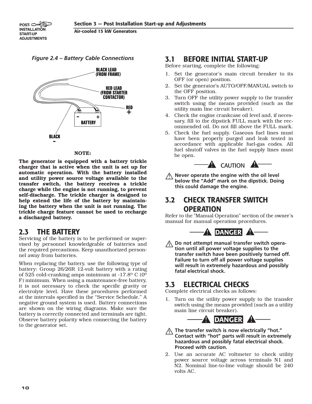
Figure 2.4 – Battery Cable Connections

NOTE:

The generator is equipped with a battery trickle charger that is active when the unit is set up for automatic operation. With the battery installed and utility power source voltage available to the transfer switch, the battery receives a trickle charge while the engine is not running, to prevent self-discharge. The trickle charger is designed to help extend the life of the battery by maintain- ing the battery when the unit is not running. The trickle charge feature cannot be used to recharge a discharged battery.

3.1BEFORE INITIAL START-UP

Before starting, complete the following:

1.Set the generator’s main circuit breaker to its OFF (or open) position.

2.Set the generator's AUTO/OFF/MANUAL switch to the OFF position.

3.Turn OFF the utility power supply to the transfer switch using the means provided (such as the utility main line circuit breaker).

4.Check the engine crankcase oil level and, if neces- sary, fill to the dipstick FULL mark with the rec- ommended oil. Do not fill above the FULL mark.

5.Check the fuel supply. Gaseous fuel lines must have been properly purged and leak tested in accordance with applicable fuel-gas codes. All fuel shutoff valves in the fuel supply lines must be open.

Never operate the engine with the oil level below the “Add” mark on the dipstick. Doing this could damage the engine.

3.2CHECK TRANSFER SWITCH

OPERATION

Refer to the "Manual Operation" section of the owner’s manual for manual operation procedures.

2.3THE BATTERY

Servicing of the battery is to be performed or super- vised by personnel knowledgeable of batteries and the required precautions. Keep unauthorized person- nel away from batteries.

When replacing the battery, use the following type of battery: Group 26/26R 12-volt battery with a rating of 525 cold-cranking amps minimum at -17.8º C (0º

F)minimum. When using a maintenance-free battery, it is not necessary to check the specific gravity or electrolyte level. Have these procedures performed at the intervals specified in the “Service Schedule.” A negative ground system is used. Battery connections are shown on the wiring diagrams. Make sure the battery is correctly connected and terminals are tight. Observe battery polarity when connecting the battery to the generator set.

DANGER

Do not attempt manual transfer switch opera- tion until all power voltage supplies to the transfer switch have been positively turned off. Failure to turn off all power voltage supplies will result in extremely hazardous and possibly fatal electrical shock.

3.3ELECTRICAL CHECKS

Complete electrical checks as follows:

1.Turn on the utility power supply to the transfer switch using the means provided (such as a utility main line circuit breaker).

DANGER

The transfer switch is now electrically “hot.” Contact with “hot” parts will result in extremely hazardous and possibly fatal electrical shock. Proceed with caution.

2.Use an accurate AC voltmeter to check utility power source voltage across terminals N1 and N2. Nominal line-to-line voltage should be 240 volts AC.

10

Page 12
Image 12
Generac Power Systems 05176-0 Before Initial START-UP, Check Transfer Switch Operation Battery, Electrical Checks

05176-0 specifications

Generac Power Systems 05176-0 is a powerful home standby generator designed to provide reliable backup power during outages. Known for its innovative technology and robust features, the 05176-0 model is part of Generac's Guardian Series, which is renowned for its reliability and ease of use.

One of the standout features of the Generac 05176-0 is its Generac G-Force engine, which is designed specifically for generator use. This automotive-grade engine is built to handle the rigors of prolonged operation, ensuring that homeowners have a dependable source of power. With a power output of 22 kW, it can handle the essential electrical loads of many homes, allowing users to power their lights, appliances, HVAC systems, and other necessary devices without interruption.

The 05176-0 comes equipped with a state-of-the-art transfer switch that automatically detects outages and begins the power restoration process within seconds. This automatic transfer switch eliminates the need for manual intervention, giving homeowners peace of mind that their power supply will seamlessly transition during a grid failure.

In terms of fuel efficiency, the Generac 05176-0 operates on either natural gas or liquid propane, providing flexibility for installation and operation. Its dual-fuel capability allows users to choose the fuel source that is most convenient and cost-effective for them.

Another notable feature is the generator’s Quiet-Test technology, which runs the generator at reduced RPMs for a self-test every week. This helps to ensure that the generator is operational and ready when needed while minimizing noise pollution in residential areas.

The model also boasts an intuitive LCD display that provides real-time information on the generator's status, including maintenance intervals and diagnostic information. This user-friendly interface simplifies monitoring and helps ensure that users can maintain optimal performance.

Moreover, the construction and design of the 05176-0 are intended for durability and weather resistance. With a robust enclosure made from high-quality materials, it is built to withstand harsh weather conditions, allowing homeowners to trust that their generator will perform reliably in any situation.

Overall, the Generac Power Systems 05176-0 stands out as a premium choice for homeowners seeking a reliable, efficient, and easy-to-use standby generator. Its combination of power output, advanced technology, and user-friendly features makes it an essential investment for anyone looking to ensure that they remain powered during outages.