Section 3 — Operation

Generac “V” Type and “Y” Type Transfer Switch

3.3.1 “Y” TYPE TRANSFER SWITCHES

3.4 VOLTAGE CHECKS

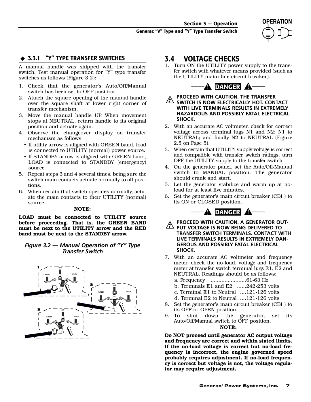
A manual handle was shipped with the transfer switch. Test manual operation for “Y” type transfer switches as follows (Figure 3.2):

1.Check that the generator's Auto/Off/Manual switch has been set to OFF position.

2.Attach the square opening of the manual handle over the square shaft at lower right corner of transfer mechanism.

3.Move the manual handle UP. When movement stops at NEUTRAL, return handle to its original position and actuate again.

4.Observe the changeover display on transfer mechanism as follows:

If utility arrow is aligned with GREEN band, load is connected to UTILITY (normal) power source.

If STANDBY arrow is aligned with GREEN band, LOAD is connected to STANDBY (emergency) source.

5.Repeat steps 3 and 4 several times, being sure the switch main contacts actuate normally to all posi- tions.

6.When certain that switch operates normally, actu- ate the main contacts to their UTILITY (normal) source.

NOTE:

LOAD must be connected to UTILITY source before proceeding. That is, the GREEN BAND must be next to the UTILITY arrow and the RED band must be next to the STANDBY arrow.

Figure 3.2 — Manual Operation of “Y” Type

Transfer Switch

1.Turn ON the UTILITY power supply to the trans- fer switch with whatever means provided (such as the UTILITY maim line circuit breaker).

DANGER

PROCEED WITH CAUTION. THE TRANSFER SWITCH IS NOW ELECTRICALLY HOT. CONTACT WITH LIVE TERMINALS RESULTS IN EXTREMELY HAZARDOUS AND POSSIBLY FATAL ELECTRICAL SHOCK.

2.With an accurate AC voltmeter, check for correct voltage across terminal lugs N1 and N2; N1 to NEUTRAL; and finally N2 to NEUTRAL (Figure 2.5 on Page 5).

3.When certain that UTILITY supply voltage is correct and compatible with transfer switch ratings, turn OFF the UTILITY supply to the transfer switch.

4.On the generator panel, set the Auto/Off/Manual switch to MANUAL position. The generator should crank and start.

5.Let the generator stabilize and warm up at no- load for at least five minutes.

6.Set the generator's main circuit breaker (CBI ) to its ON or CLOSED position.

DANGER

PROCEED WITH CAUTION. A GENERATOR OUT- PUT VOLTAGE IS NOW BEING DELIVERED TO TRANSFER SWITCH TERMINALS. CONTACT WITH LIVE TERMINALS RESULTS IN EXTREMELY DAN- GEROUS AND POSSIBLY FATAL ELECTRICAL SHOCK.

7.With an accurate AC voltmeter and frequency meter, check the no-load, voltage and frequency meter at transfer switch terminal lugs E1, E2 and NEUTRAL. Readings should be as follows:

a.Frequency ........................61-63 Hz

b.Terminals E1 and E2 ......242-253 volts

c.Terminal E1 to Neutral ....121-126 volts

d.Terminal E2 to Neutral ....121-126 volts

8.Set the generator's main circuit breaker (CBI ) to its OFF or OPEN position.

9.To shut down the generator, set its Auto/Off/Manual switch to OFF position.

NOTE:

Do NOT proceed until generator AC output voltage and frequency are correct and within stated limits. If the no-load voltage is correct but no-load fre- quency is incorrect, the engine governed speed probably requires adjustment. If no-load frequen- cy is correct but voltage is not, the voltage regula- tor may require adjustment.

Generac® Power Systems, Inc. 7

Page 9
Image 9
Generac Power Systems 09230-0, 09227-0, 09229-0, 09228-0 owner manual Voltage Checks

09229-0, 09228-0, 09230-0, 09227-0 specifications

Generac Power Systems has established itself as a leading manufacturer in the power generation industry, and models such as the Generac Power Systems 09227-0, 09230-0, 09228-0, and 09229-0 exemplify their commitment to innovation and reliability. These models are specifically designed for residential use, providing uninterrupted power during outages and ensuring that homes remain functional and comfortable.

One of the standout features of these Generac models is their use of advanced automatic transfer switch technology. This seamless transition between utility power and generator power minimizes downtime during power outages, allowing homeowners to maintain their daily routines without interruption. The automatic transfer switches are equipped with sophisticated monitoring systems that can detect power loss and engage the generator within seconds.

Furthermore, the engines in these models are designed for optimal efficiency, often featuring a heavy-duty design that ensures longevity and reliability. This durability is complemented by Generac's G-Force engine technology, which is designed for rigorous use and is tested under extreme conditions. These engines are also built to run on natural gas or propane, providing flexibility depending on fuel availability and user preference.

In terms of noise reduction, Generac has incorporated innovative sound-dampening technology, ensuring that these generators operate quietly. This is particularly important for residential areas where noise pollution can be a concern.

The models also come equipped with user-friendly interfaces, making it easy for homeowners to monitor and control their power systems. Digital displays provide real-time information on power production and battery status, while intuitive controls allow for straightforward operation and maintenance.

Additionally, the Generac Power Systems 09227-0, 09230-0, 09228-0, and 09229-0 models feature robust safety precautions. These include automatic shutdown mechanisms that activate in the event of low oil pressure or overheating, thus protecting both the generator and the home.

With their combination of efficiency, reliability, and advanced technology, the Generac Power Systems 09227-0, 09230-0, 09228-0, and 09229-0 offer homeowners a practical solution for backup power needs. They reflect Generac's ongoing mission to provide dependable power solutions that enhance the quality of life, particularly during unpredictable weather events or public utility failures.