
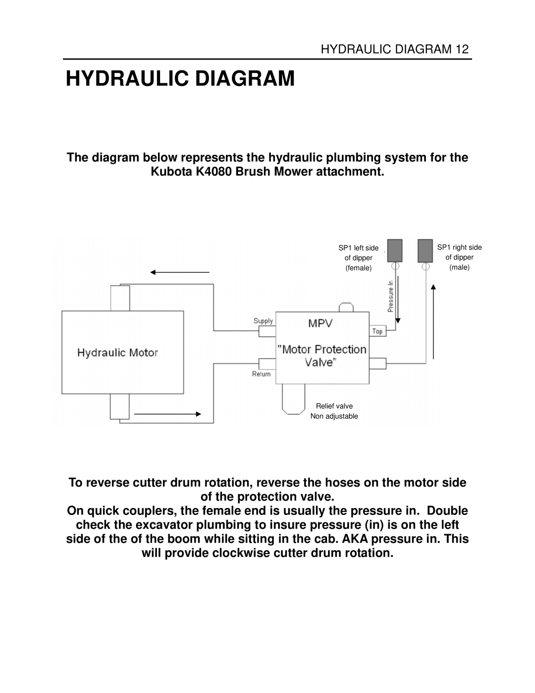
K4080 specifications
Generac Power Systems has established itself as a leader in the power generation industry, providing reliable solutions for residential, commercial, and industrial applications. Among its notable offerings is the Generac K4080, a robust and versatile generator designed to meet a wide range of power needs.The K4080 is engineered with advanced technology, making it ideal for backup and prime power applications. It is equipped with a powerful engine that delivers a peak output of 40 kW, providing ample power for heavy-duty demands. This generator operates on a diesel fuel system, which is not only efficient but also ensures lower operating costs and extended run times. The K4080 is designed to handle multiple loads, making it suitable for scenarios such as construction sites or events where temporary power is essential.
One of the key features of the K4080 is its noise reduction system. The generator is built with sound-attenuated enclosures that minimize operational noise, making it a viable choice for residential areas and locations with noise restrictions. This quality ensures that users can operate the generator without disturbing the surrounding environment, a factor that is increasingly important in today's urban settings.
Another standout aspect of the K4080 is its intuitive control panel, which provides real-time information about the generator's operational status. Users can easily monitor critical metrics such as voltage output, frequency, and operational hours, making it simple to manage power consumption and maintenance schedules effectively. Furthermore, the generator’s automatic startup feature ensures that it can kick in at a moment's notice during power outages, providing peace of mind for homeowners and businesses alike.
The K4080 also incorporates advanced safety features, including overload protection and low oil shutdown, to safeguard both the machine and its operators. These safety systems are crucial for ensuring the longevity of the generator and preventing accidents during operation and fuel management.
In summary, the Generac K4080 is a sophisticated power generation solution that combines high output, reliability, and safety. With its advanced technologies and design, it offers users a dependable source of power for various applications, making it a preferred choice in the market. Whether for home backup or commercial use, the K4080 stands out for its robust performance and user-friendly features.