GA-3PXSL-RH Motherboard
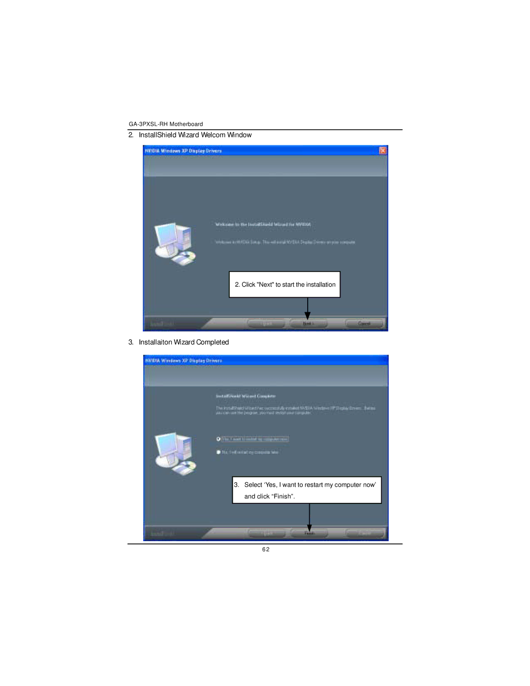
2. InstallShield Wizard Welcom Window
2. Click "Next" to start the installation
3. Installaiton Wizard Completed
3.Select ‘Yes, I want to restart my computer now’ and click “Finish”.
6 2
2. Click "Next" to start the installation
3. Installaiton Wizard Completed
3.Select ‘Yes, I want to restart my computer now’ and click “Finish”.
6 2