Page
Page
Supplementar y Infor mation
Declaration of Conformity
Declaration of Conformity
USER’S Manual
Table of Content
Appendix
Revision History
Installing the motherboard to the chassis…
Introduction
Summary of Features
LAN
Only for GA-8IDML
GA-8IDML Series Motherboard Layout
GA-8IDML-LE Motherboard Layout
Step
Hardware Installation Process
Socket Actuation Lever Pin1 indicator
Install the Central Processing Unit CPU
CPU Heat Sink Installation
Sdram
Install memory modules
Install expansion cards
? Parallel Port and Serial Ports COMA/COMB
Connect ribbon cables, cabinet wires, and power supply
? PS/2 Keyboard and PS/2 Mouse Connector
? Game /MIDI Ports
? Audio Connectors
? USB/LAN Connector
Connectors Introduction
CPU FAN
G Cpufan / Pwrfan / SYS FAN Connector
ATX Power
AUX12V Power Connector
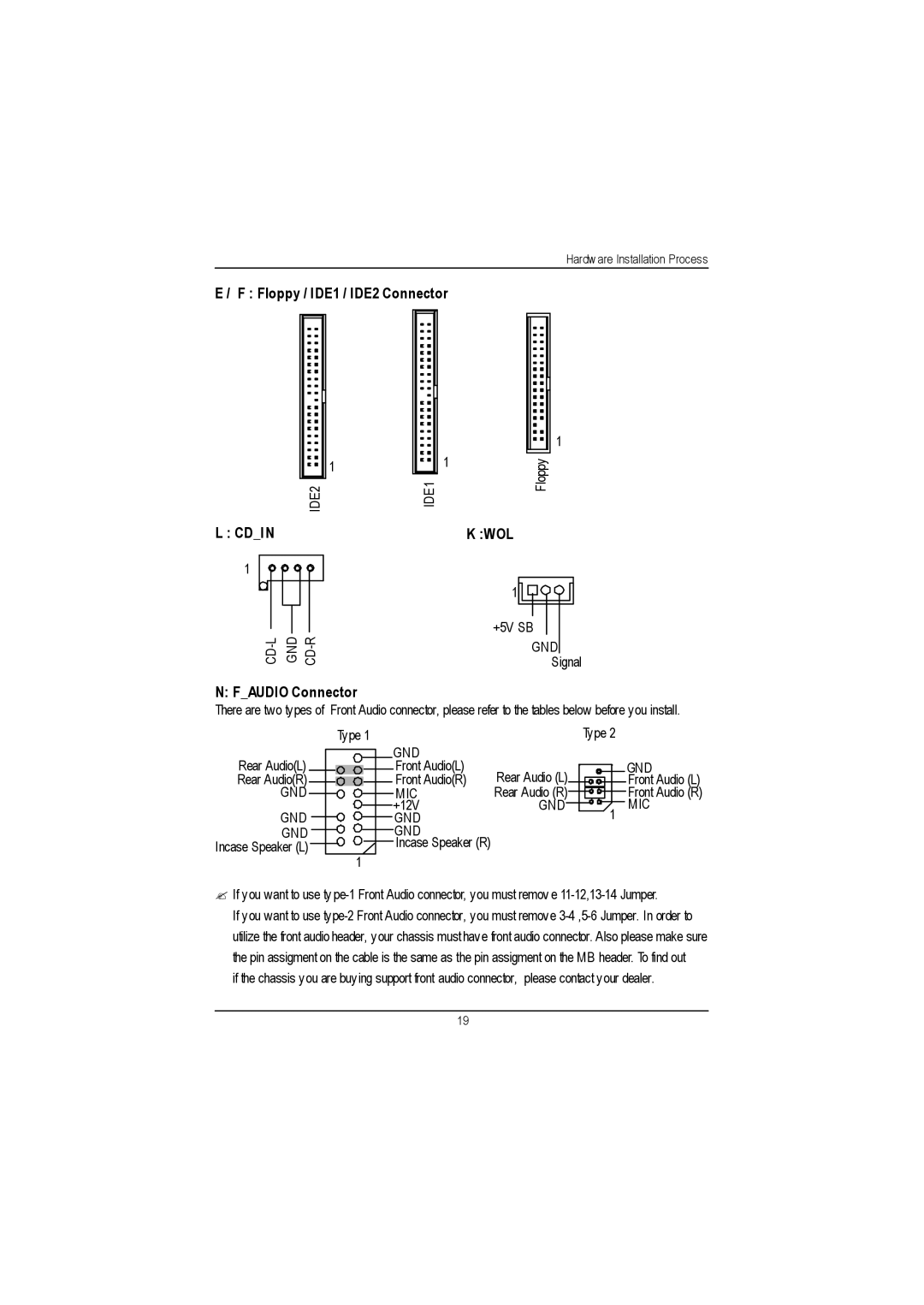
Faudio Connector
Floppy / IDE1 / IDE2 Connector
Usbvs PS/2 USB Wake Up selection
JBattery
Front USB
Bios Setup
Main Menu For example Bios Ver. F1
? Load Optimiz ed Defaults
? Power Management Setup
? PnP/PCI Configurations
? Load Fail-Safe Defaults
EGA / VGA
Standard Cmos Features
Date
Drive a / Drive B
Time
IDE Primary Master, Slave / Secondary Master, Slave
EGA/VGA
Floppy 3 Mode Support for Japan Area
Video
Halt on
Extended Memory
Memory
Base Memory
Cdrom
Advanced Bios Features
First / S econd / Third Boot device
HDD-0
MPS Ver sion Control For OS
Boot Up Fl oppy Seek
Boot Up NumLock
Passwor d Check
CAS latency Time
Advanced Chipset Features
Configure Dram Timing
Active to Precharge Delay
Delay Transaction
Sdram RAS# to CAS# delay
Refresh Mode Select
Dram Data Integrity Mode
AGP Graphics Aperture Size
Delay Prior to Thermal
AGP
Integrated Peripherals
IDE Primary Slave PIO for onboard IDE 1st channel
On-Chip Primary PCI IDE
On-Chip Secondary PCI IDE
IDE Primary Master PIO for onboard IDE 1st channel
IDE Secondary Master Udma
IDE Secondary Slave PIO for onboard IDE 2nd channel
IDE Primary Master Udma
IDE Primary Slave Udma
AC97 Audio
USB Keyboard Support
USB Mouse Support
Init Display First
Onboard FDC Controller
Mouse Power On
Keyboard Power On
KB Power on Password
RxD, TxD Active
Uart Mode Select
IR Transmis sion Delay
UR2 Dupl ex Mode
Parall el Port EPP Type
Use IR Pins
Parallel Port Mode
OnBoard Par allel port
PCI PIRQA-D#
Power Management Setup
S1POS
Dpms
Video off Method
Power Management
Acpi Sleep Type
USB Dev Wakeup From S3
Soft-off by PWR-BTTN
Suspend Mode
HDD Power Down
Modem Use IRQ
Secondary IDE 0/1
RTC Alarm Power On
Modem Ring On/ Wak eOnLAN
Primary IDE 0/1
PCI1 IRQ Assignment
PnP/PCI Configurations
Resources Controlled by
IRQ Res ources 3,4,5,7,9,10,11,12,14,15
PCI3 IRQ Assignment
Current Voltage V Vcore / VCC18 / +5V / ±12V
Current S ystem / CPU Temperature C / F
Current CPU FAN / Power FAN / System FAN Speed RPM
PC Health Status
Fan Fai l Warning CPU / POWER/ System
CPU Warning Temperature
CPU Host Frequency
Frequency/Voltage Control
CPU Clock Ratio
CPU Host Cl ock Control
Load Fail-Safe Defaults
Load Fail-Safe Defaults
Load Optimiz ed Defaults
Load Optimized Defaults
Enter Password
Set Supervisor/User Password
? Y
Save & Exit Setup
Quit Without Saving Y/N? N
Exit Without Saving
Performance List
Block Diagram
Four Speaker & Spdif Introduction
Four Speaker Introduction What is Four Speaker?
Four Speaker Application
Microsoft Windows Me setup procedure
How to use SPDIF?
Spdif Introduction What is SPDIF?
Technical Reference
Gigabyte announces @ Bios Windows Bios live update utility
@ Bios Introduction
Gigabyte announces EasyTuneIII Windows overdrive utility
Easy TuneIIITM Introduction
Appendix
Appendix B Creative CT5880 Chipset Driver Installation