User Guide
Page
User Guide
Margay Display Wall Unit
Page
Iii
Page
Feedback About Manuals
Page
Contents
Troubleshooting …
Basic Information About Margay
Accessories For Margay
Check what you received with the Margays
Short side-to-side bolt DVI cable VGA cable Remote Control
Your Safety and Margay’s Safety
Page
Page
Installing
What You Will Do
Installation
Configuration
Page
Installing the VIM Video Input Module
One of 4 screws
Installing the Big Picture Key
Page
Laying the first row
Why is straight so important?
Building the Wall, First Row
Page
Building the Wall, Second Row and Up
Continuing to build the wall
Safety with high or tilted walls
Inverting the picture and menus
Screens when inverted
Building a Banner, Upside Down
Page
Connections
Page
Limits of loop-thru
Digital Out connector carries the selected input
Connections, Analog & Digital Sources
Out
Composite video
Video is a option installed in the field
Connections, Video Sources
Video
Page
Connections, Power
AC loop-thru means you won’t need as many mains sockets
AC power in and out
Connections, Control RS232 & RS485
Connect to the computer
Page
Avoiding damage to the screens
Installing and Removing Screens
About no-mullion screens
Avoiding gaps between screens
Dont do this
First
Installing the Screens
Final adjustment
Then
Page
Steps to remove a single screen from a Margay wall
Opening or Removing a Screen
Hints
Then this edge
Opening a Screen Temporarily for Work
Margay screen props open for work from the front
Aligning and Adjusting
What if you CAN’T move the image enough?
Adjusting Margay’s Engine Important Step
Aligning the optical engine
Loosen these two nuts
Page
Alignment Dashes
Selecting the source
Adjusting Each Margay To Its Source
How does Input Level relate to Color Balance
What does Input Level do?
Page
Adjusting to Computers, Analog RGB
Best way to adjust levels is the semi-automatic method
Page
Adjusting Input Levels Manually
Adjusting levels manually
Page
Adjusting to Computer Sources, Digital
Page
Adjusting with any picture
Adjusting to Video Sources
Adjusting the picture
Adjusting with color bars
Saturation Match
Color Balancing
Color Balancing a Wall of Margays
Color Balancing can be done before or after Input Levels
Set White Boost to Off Set Test Pattern to White
Brightness
Spreading One Picture Over a Wall
Using an external processor
Using Clarity’s Big Picture
Scale Mode, Justify and Border Color…
Page
Scaling and Cropping
No Big Picture key
Zoom and Position
Page
What is the DMD?
Viewport Adjustment
Viewport menus adjust the image on the DMD
What is Viewport?
Page
How automatic save works
How to recall a memory slot
Saving Your Work & Recalling a Memory
Manually saving to memory slots
Enter
Memory
Memory What Is Saved? And Where?
Switching modes
Global parameters
Switching input connectors
Possible issue with Input specific memory
Memory slots
Page
Operating
Selecting a Source
Page
Shut down sequence
Normal Start Up
Start up sequence
Page
Beeper
Remote control
Controlling Margay with Remote
If the remote doesn’t work
Page
Controlling Margay with RS232/RS485
Connect the RS232 In to the computer. Loop thru with RS485
Page
Asset Tag and Display Status
Display Status menu information
Troubleshooting
Troubleshooting Tips
Margay has several troubleshooting aids
Page
Automatic On Screen code display
Reading the On Screen Code
Turning on the On Screen code
Margay On-Screen Codes
Reading the LEDs
To see LEDs
LEDs in Margay
Page
Maintenance for Margay
Changing a Lamp
When should I change the lamp?
How to change the lamp from the front
You can change the lamp from the front or the rear
Removing the lamp from the rear
Resetting lamp hours
How to maintain lamp life
Replacing the lamp
Changing the Air Filter
Clean, cool air is essential for proper Margay operation
When should I change the air filter?
Removing the air filter from the front
Removing the air filter from the rear
Cleaning the Screen and Mirrors
Reference Section
Menu Trees …
Menu Trees
Picture
Picture Source Select
Input Levels Analog Sources
Input Levels Digital Sources
Input Levels Video Sources
Size & Position
Size & Position
Aspect Ratio & Wall
Memory
Memory Recall
Memory Save
Diagnostics Display Status
Diagnostics RS232 & RS485 Status
Diagnostics Test Patterns
Diagnostics Setup Summary
Diagnostics Hours
Advanced Options Color Balance
Advanced Options Miscellaneous Options
Advanced Options Lamp Settings
Advanced Options Serial Port Settings
Advanced Options Auto Setup Options
Advanced Options Engine Alignment
Advanced Options Menu Options
Program Information
Remote Control Buttons
Page
Page
Page
All dimensions are in inches
Drawings
121
122
123
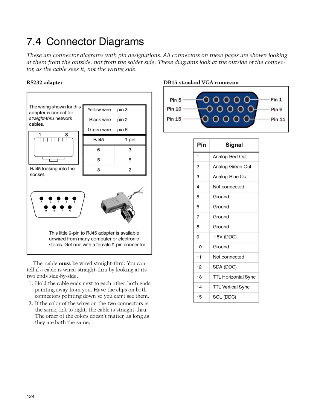
Connector Diagrams
RS232 adapter DB15 standard VGA connector
Video connector
DVI-I connector
Glossary of Terms
Term Meaning
See also YPbPr
VIM
129
Specifications for Margay
Mechanical Specification Maximum Minimum Typical
Optical Specification Maximum Minimum Typical
Environmental Specification Maximum Minimum Typical
133
Regulatory Certifications
FCC Regulations
Index
136
137
138
C D
140
But first
Describe the problem
My Clarity Reseller is
Un-helpful language