spindle lock engages and locks the spindle. Use the pin wrench (11) to unscrew the outer flange (13). Note that this flange unscrews anticlockwise. (Fig. I)
2. Remove the outer flange (13) (Fig. J) and the used
J |
| K |
|
|
|
disc.(Fig. K)
3.Clean the flanges (13 and 15) and check the new disc.
4.Ensure that the
inner flange (15) is on theL
spindle and located correctly. The two machined flat sections on the inner flange
(15)must face the angle grinder and locate in the matching positions on the spindle. (Fig. L)
Fit the new disc, ensuring that
the disc is correctly located on the inner flange.
NOTE. Make sure that you select the correct disc for the planned application, i.e. fit a metal grinding disc for cutting metal, a masonry grinding disc for grinding masonry, a cutting disc for cutting, etc.
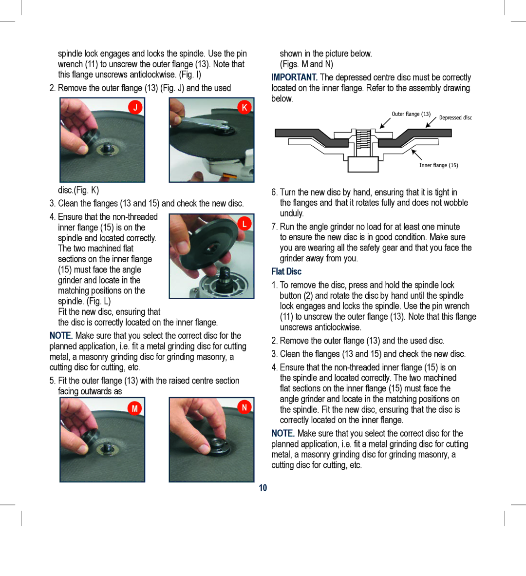
5.Fit the outer flange (13) with the raised centre section facing outwards as
M |
| N |
|
|
|
shown in the picture below. (Figs. M and N)
IMPORTANT. The depressed centre disc must be correctly located on the inner flange. Refer to the assembly drawing below.
6.Turn the new disc by hand, ensuring that it is tight in the flanges and that it rotates fully and does not wobble unduly.
7.Run the angle grinder no load for at least one minute to ensure the new disc is in good condition. Make sure you are wearing all the safety gear and that you face the grinder away from you.
Flat Disc
1.To remove the disc, press and hold the spindle lock button (2) and rotate the disc by hand until the spindle lock engages and locks the spindle. Use the pin wrench (11) to unscrew the outer flange (13). Note that this flange unscrews anticlockwise.
2.Remove the outer flange (13) and the used disc.
3.Clean the flanges (13 and 15) and check the new disc.
4.Ensure that the
NOTE. Make sure that you select the correct disc for the planned application, i.e. fit a metal grinding disc for cutting metal, a masonry grinding disc for grinding masonry, a cutting disc for cutting, etc.
10
