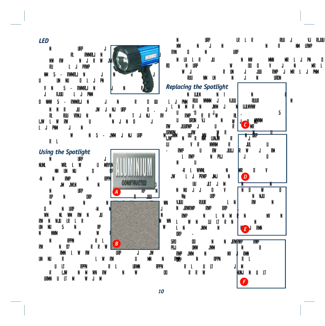
LED
The spotlight has 3 LED indicators
(4)which indicates battery level when in operation and status whilst charging.
Red LED indicates battery is in a low level of charge.
Amber LED indicates battery is partially charged.
Green LED indicates battery is fully charged.
There is also an area light (GMC Part
To turn the LED and area light on and off, depress the light switch (2)
Using the Spotlight
The Spotlight has a digital electronic control dimmer with three levels of brightness.
Depressing the trigger switch
(1) advances the brightness of
the spotlight to dim, brighter, A brightest (fig. A). This allows the user to set the desired brightness
of the light. Depressing trigger at one second intervals to allow the internal circuits to set to the next level. Lower brightness operation extends the run time.
The Trigger Switch may be locked | B | |
in the ON position (fig. B) to | ||
| ||
provide continuous light at any |
|
level without continuously depressing the Trigger Switch.
To lock trigger switch slide trigger switch lock upwards. This can be done in the on or off position. To release lock, slide lock downwards.
10
The spotlight’s circuitry will automatically dim the light when the battery’s power is reducing. This preserves the run time of the spotlight.
The circuit also prevents deep discharge of the battery even if the light turns off from battery discharge. Recharge as soon as possible, as allowing a discharged battery to remain so will reduce the battery life.
Replacing the Spotlight
To replace the H3 type 6V bulb you will need a small Phillips type screwdriver and a replacement bulb (GMC Part
Bulb life may be shortened by
installing a bulb with dirt or C
fingerprints on it. The bulb can be wiped clean with a
cloth moistened with alcohol. During bulb installation, avoid touching the glass part of the bulb
1. Disconnect the unit from | D |
any charging adapters. |
2.Pull backward the rubber bezel away from the front of the spotlight to reveal two small Phillips screws in the Retaining Ring (fig. C).
3.Using the screwdriver, remove
screws and set them aside | E |
(fig. D). |
|
|
4.Lift off the retaining ring, glass lens and rubber “O” ring and set them aside (fig. E & F).
F
