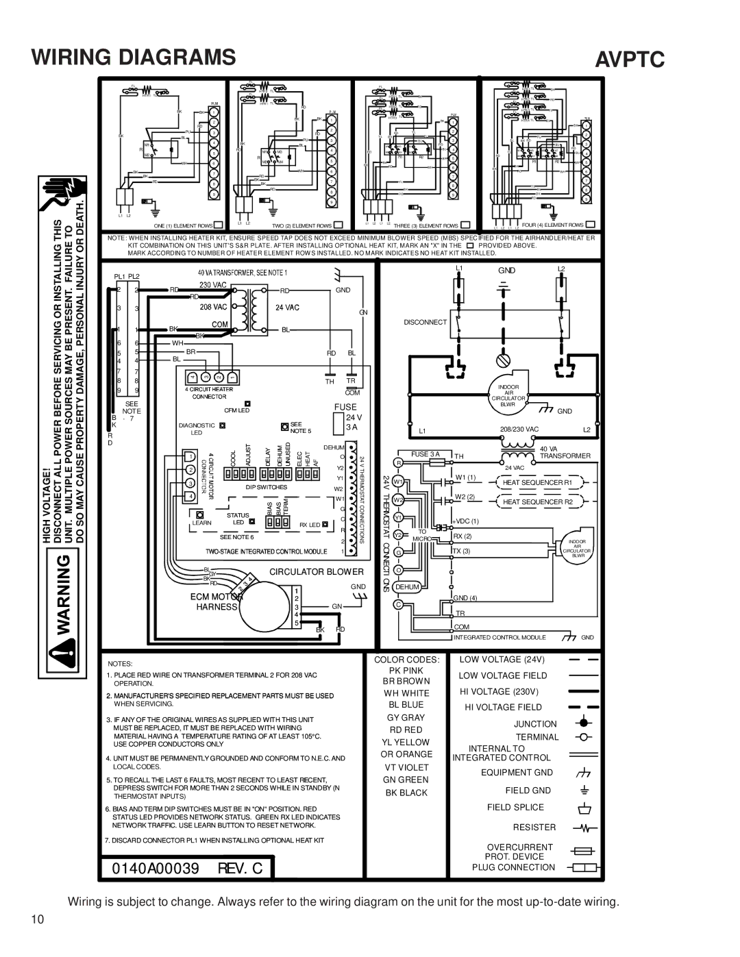
WIRING DIAGRAMS

AVPTC

HIGH VOLTAGE! DISCONNECT ALL POWER BEFORE SERVICING OR INSTALLING THIS UNIT. MULTIPLE POWER SOURCES MAY BE PRESENT. FAILURE TO DO SO MAY CAUSE PROPERTY DAMAGE, PERSONAL INJURY OR DEATH.


FL


FL


FL


HTR 1 TL


B K


HTR 2

TL


FL


HTR1 TL


FL


HTR 1 TL


FL


HTR 2 TL


RD


TL


FL


HTR 1


HTR2 TL


BK

BK 1


RD


FL

RD


FL

HTR 3 TL


Y L


BK

BK

1


HTR3 TL


BK


HTR 4 TL


BL


2


1


RD


2


B K

1


PU

3


RD


RD

Y L


2


BK


2

BL


Y L

B K


P U


PU


PU


3


3


M1

4

BK


B L

RD


B L

B K RD


B L


3


BL


M1

M3

M1


RD


R


RD

M1

M3


4

RD


M2

M4

M2

B L

4


Y L

M1

M3

M5

M7


M2

5


RD


B L

4


R


R1

R2


5


M2

M4

M6

M8


M4


5


BR


R1


R2


WH

6


M2


BK

BK


B K


BR

5


RD


WH

6

B K


WH


6


BK

7


RD


WH

6


BK


RD


7


RD

8


BK


7


Y L


7


BK


8


Y L


RD


8


B K


B L


8


9


RD


9


B K


9


RD


9


L1

L2


ONE (1) ELEMENT ROWS

L1 L2


TWO (2) ELEMENT ROWS

L1 L2 L1

L2

THREE (3) ELEMENT ROWS

L1 L2

L1

L2

FOUR (4) ELEMENT ROWS


NOTE: WHEN INSTALLING HEATER KIT, ENSURE SPEED TAP DOES NOT EXCEED MINIMUM BLOWER SPEED (MBS) SPECIFIED FOR THE AIRHANDLER/HEAT ER

KIT COMBINATION ON THIS UNIT'S S&R PLATE. AFTER INSTALLING OPTIONAL HEAT KIT, MARK AN "X" IN THE PROVIDED ABOVE. MARK ACCORDING TO NUMBER OF HEATER ELEMENT ROW S INSTALLED. NO MARK INDICATES NO HEAT KIT INSTALLED.

PL1 PL2


L1

GND


L2


2

2

RD


RD


GND


RD


3

3


GN


1

1

BK


BL


DISCONNECT


BK


6

6

WH


5

5

BR


RD

BL


4

4

BL


7

7

4


3


2

1


8

8


TH

TR


INDOOR


9

9


COM


AIR


SEE


CIRCULATOR


CFM LED


FUSE


BLWR


GND


NOTE


B


24 V


- 7


SEE


K


DIAGNOSTIC


3 A


L1


208/230 VAC


L2


NOTE 5


R


LED


D


COOL


ADJUST

DELAY

DEHUM UNUSED

ELEC HEAT AF


24V


R


40 VA


DEHUM


FUSE 3 A


1


O


TH


TRANSFORMER


2


SEE NOTE 6

BIAS

BIAS TERM


Y2

THERMOSTATCONNECTIONS

24VTHERMOSTAT


MICRO

RX (2)

24 VAC


INDOOR


2


3


DIP SWITCHES


Y1


W1


W1 (1)

HEAT SEQUENCER R1


W2


W2 (2)


4


W1


W2


HEAT SEQUENCER R2


G


STATUS


C


Y1


+VDC (1)


LEARN


LED


RX LED


R


TO


Y2


GND

CONNECTIONS


2


1

DEHUM

TX (3)


AIR


G


CIRCULATOR


BLWR


GY


CIRCULATOR BLOWER


O


BL


BK


4


RD

1


3


1


GND (4)


2


ECM MOTOR


C


HARNESS


3

GN


TR


4


5

RD


COM


BK


GND


INTEGRATED CONTROL MODULE


NOTES:

1.PLACE RED WIRE ON TRANSFORMER TERMINAL 2 FOR 208 VAC OPERATION.

2.MANUFACTURER'S SPECIFIED REPLACEMENT PARTS MUST BE USED WHEN SERVICING.

3.IF ANY OF THE ORIGINAL WIRES AS SUPPLIED WITH THIS UNIT MUST BE REPLACED, IT MUST BE REPLACED WITH WIRING MATERIAL HAVING A TEMPERATURE RATING OF AT LEAST 105°C. USE COPPER CONDUCTORS ONLY

4.UNIT MUST BE PERMANENTLY GROUNDED AND CONFORM TO N.E.C. AND LOCAL CODES.

5.TO RECALL THE LAST 6 FAULTS, MOST RECENT TO LEAST RECENT, DEPRESS SWITCH FOR MORE THAN 2 SECONDS WHILE IN STANDBY (N THERMOSTAT INPUTS)

6.BIAS AND TERM DIP SWITCHES MUST BE IN "ON" POSITION. RED STATUS LED PROVIDES NETWORK STATUS. GREEN RX LED INDICATES NETWORK TRAFFIC. USE LEARN BUTTON TO RESET NETWORK.

7.DISCARD CONNECTOR PL1 WHEN INSTALLING OPTIONAL HEAT KIT

0140A00039 REV.C

COLOR CODES:

LOW VOLTAGE (24V)

PK PINK

LOW VOLTAGE FIELD

BR BROWN

HI VOLTAGE (230V)

WH WHITE

BL BLUE

HI VOLTAGE FIELD

GY GRAY

JUNCTION

RD RED

TERMINAL

YL YELLOW

INTERNAL TO

OR ORANGE

INTEGRATED CONTROL

VT VIOLET

EQUIPMENT GND

GN GREEN

FIELD GND

BK BLACK


FIELD SPLICE


RESISTER


OVERCURRENT


PROT. DEVICE


PLUG CONNECTION

Wiring is subject to change. Always refer to the wiring diagram on the unit for the most up-to-date wiring.

10

Page 10
Image 10
Goodman Mfg AVPTC183014, AVPTC313714 service manual Wiring Diagrams, Avptc

AVPTC313714, AVPTC183014 specifications

Goodman Manufacturing is a prominent name in the HVAC industry, known for its commitment to quality and performance. Among its impressive lineup is the AVPTC183014 and AVPTC313714 series of air handlers. These models are designed to provide superior comfort, efficient energy use, and quiet operation, making them excellent choices for residential HVAC systems.

The Goodman AVPTC183014 is a variable speed air handler that integrates seamlessly with a Goodman outdoor unit. Rated at 1.5 tons, this model is best suited for medium-sized homes. The key feature of this unit is its advanced variable speed motor. This technology allows the air handler to adjust its speed based on the cooling or heating demand. This results in enhanced energy efficiency, as the unit consumes less electricity during partial load conditions.

On the other hand, the Goodman AVPTC313714 boasts a larger capacity of 2.5 tons, making it suitable for larger spaces. Like its counterpart, this model also features a variable speed blower motor, which enhances comfort and provides consistent airflow throughout the home. Both units excel in humidity control, ensuring optimal indoor air quality. The variable speed technology allows for better moisture removal, leading to a more comfortable living environment.

Another notable characteristic of the AVPTC series is its compatibility with Goodman’s Energy Star-rated condensing units. This synergy between air handlers and outdoor units enhances the overall efficiency of the HVAC system. The all-aluminum coil construction used in both models ensures durability and resistance to corrosion, thereby extending the lifespan of the units.

Installation is simplified thanks to the versatile design of these air handlers. They are engineered for easy access to components, which facilitates maintenance and service. Additionally, they come with a robust warranty, providing peace of mind to homeowners regarding their investment.

In summary, the Goodman AVPTC183014 and AVPTC313714 air handlers offer exceptional performance with advanced technologies. Their variable speed motors, energy efficiency, and superior humidity control make them ideal for residential use. With durable construction and easy installation, these models exemplify Goodman’s commitment to delivering reliable and effective HVAC solutions.