20
Wiring is
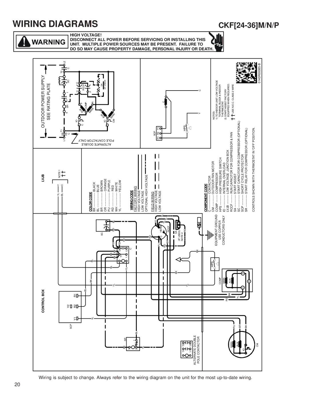
CONTROL BOX
|
|
| LVJB | |
|
|
|
|
|
YL |
| Y | ||
OUTDOOR POWER SUPPLY
SEE RATING PLATE
WIRING
subject to change. Always refer to
| SCP | Y2 |
|
|
|
|
|
|
|
|
|
|
|
| |
| Y1 | R2 | R1 |
|
|
|
|
|
|
| BL |
|
|
|
|
| YL |
| BK | BL |
|
|
|
|
|
|
|
|
| ||
|
|
|
|
|
|
| SC |
|
|
| BL | BK | RD | RD BL | |
|
|
| YL | BK | BK | ||
|
|
|
| T1 | T2 RD |
| |
|
|
|
|
|
| RD | |
BK | SR |
| YL | L1 | L2 |
| |
|
|
|
| ||||
5 |
|
|
|
| |||
|
|
|
|
|
|
| |
BL |
| NOTE 1 | ||||||
| C |
|
|
|
|
|
| |
|
|
|
|
|
|
|
|
|
COLOR CODE
BK | BLACK |
BL | BLUE |
BR | BROWN |
OR | ORANGE |
PU | PURPLE |
RD | RED |
WH | WHITE |
YL | YELLOW |
T1
L1 ![]()
![]()
C
POLE CONTACTOR ONLY
ALTERNATE DOUBLE
|
|
|
|
| 5 |
| SR | 2 | 1 | SC |
|
|
|
|
|
|
|
| |||
| IO |
|
|
|
|
|
|
| H | C |
C |
|
|
|
| A | U | X | S | RCCF | |
|
|
|
|
|
| |||||
|
|
|
|
|
| COMP | ||||
|
|
|
|
|
|
|
|
| ||
|
|
|
|
|
| I |
| F |
| |
|
|
|
|
| M |
|
|
|
| |
|
|
|
|
| A | R |
|
| ||
|
|
|
|
|
| N |
|
| ||
|
|
| A | U | X |
|
|
|
| SA |
| IO |
|
|
|
|
|
| (IF USED) | ||
|
|
|
|
|
|
|
| |||
|
| M |
|
|
|
|
|
| ||
| CM | A |
|
|
|
|
| |||
|
| I |
|
|
|
|
| |||
|
|
|
| N |
|
|
|
|
| |
T2
![]()
![]()
![]() L2 C
L2 C
HIGH VOLTAGE! DISCONNECT ALL POWER UNIT. MULTIPLE POWERSOURCES DO SO MAY CAUSE PROPERTY |
DIAGRAMS
the wiring diagram on the unit for the most up-to-date wiring.
|
|
|
| C |
|
|
|
2 | 1 | BL |
|
|
|
|
|
|
|
|
|
|
| ||
YL |
|
|
|
|
|
| |
|
|
|
| RD |
|
|
|
|
|
|
|
|
| YL |
|
|
|
|
| PU | HERM |
|
|
|
|
|
| C |
| YL | |
|
|
|
| RD | F | YL | |
|
|
|
|
| |||
|
|
|
| BR | RCCF | YL |
|
|
|
|
|
|
|
| |
|
|
| BK |
| SA |
|
|
|
|
|
| (IF USED) |
|
| |
T1 | T2 |
|
| NOTE 2 |
|
| |
|
|
| RD |
|
| ||
|
|
| YL |
|
|
| |
L1 | L2 |
|
|
|
|
| |
|
|
|
|
|
| ||
ALTERNATE DOUBLE |
|
| BK |
|
|
| |
POLE CONTACTOR |
|
|
|
|
| ||
|
|
|
| HPS |
|
|
|
|
|
|
| EQUIPMENT GROUND | |||
|
|
| COMP | USE COPPER |
| ||
|
| RD | MAIN | CONDUCTORS ONLY | |||
|
|
|
|
|
|
| |
| MAIN | BK | AUX |
|
|
|
|
| PU |
|
|
|
|
| |
|
|
|
|
|
|
| |
| AUX | YL |
|
|
|
|
|
|
| BR |
|
|
|
|
|
IO |
| C | S |
|
|
|
|
| BK |
|
|
|
|
| |
|
|
|
|
|
|
| |
|
|
| R |
|
|
|
|
| CM |
|
|
|
|
|
|
WIRING CODE |
|
| |
FACTORY WIRING |
|
| |
HIGH VOLTAGE |
|
| |
LOW VOLTAGE |
|
| |
OPTIONAL HIGH VOLTAGE |
|
| |
FIELD WIRING | SCP |
| |
HIGH VOLTAGE |
| ||
R1 R2 | Y1 | ||
LOW VOLTAGE | |||
|
| ||
|
| C |
|
|
|
|
| HPS |
|
|
|
|
|
|
|
|
|
|
| |||||
|
|
|
|
|
|
|
|
|
|
|
|
|
|
|
|
|
|
|
| ||
|
|
|
|
|
|
|
|
|
|
|
|
|
|
|
|
|
|
|
|
| |
|
|
|
|
|
|
|
|
|
|
|
|
|
|
|
|
|
|
|
|
| |
|
|
|
|
|
|
|
|
|
|
|
|
|
|
|
|
|
|
|
|
| |
|
|
|
|
|
|
|
|
|
|
|
|
|
|
|
|
| Y |
| C | ||
COMPONENT CODE |
|
|
|
|
|
|
|
|
|
|
|
| |||||||||
C | CONTACTOR |
|
|
|
|
|
|
|
|
|
|
|
|
|
|
|
|
|
| ||
OUTDOOR FAN MOTOR |
|
|
|
|
|
|
| NOTES: |
|
| |||||||||||
COMP | COMPRESSOR | 1) TO INDOOR UNIT LOW VOLTAGE | |||||||||||||||||||
HPS | HIGH PRESSURE SWITCH |
|
|
| TERMINAL BLOCK & INDOOR | ||||||||||||||||
IO | INTERNAL OVERLOAD |
|
|
| THERMOSTAT. |
|
| ||||||||||||||
2) START ASSIST FACTORY | |||||||||||||||||||||
LVJB | LOW VOLTAGE JUNCTION BOX | ||||||||||||||||||||
|
|
| EQUIPPED WHEN REQUIRED. | ||||||||||||||||||
RCCF | RUN CAPACITOR FOR COMPRESSOR & FAN |
|
|
|
|
|
|
| USE N.E.C. CLASS 2 WIRE | ||||||||||||
START ASSIST |
|
|
|
|
|
|
|
|
|
|
| ||||||||||
SC | START CAPACITOR FOR COMPRESSOR (OPTIONAL) |
|
|
|
|
|
|
|
|
|
|
| |||||||||
SCP | SHORT CYCLE PROTECTOR |
|
|
|
|
|
|
|
|
|
|
| |||||||||
SR | START RELAY FOR COMPRESSOR (OPTIONAL) |
|
|
|
|
|
|
|
|
|
|
| |||||||||
CONTROLS SHOWN WITH THERMOSTAT IN 'OFF' POSITION.
DAMAGE, PERSONAL INJURY OR DEATH | BEFORE SERVICING OR INSTALLING THIS MAY BE PRESENT. FAILURE TO |
. |
|