Goodman Mfg GMH95 service manual Furnace Specifications

Models: GMH95

1 15
Download 15 pages 2.73 Kb
Page 11
Image 11

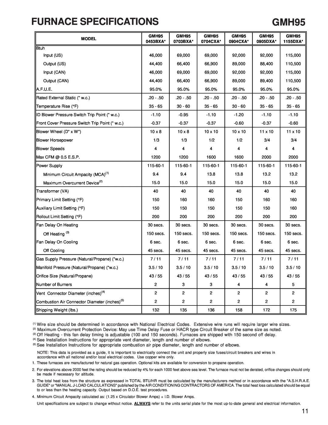
FURNACE SPECIFICATIONS


GMH95


MODEL

GMH95

GMH95

GMH95

GMH95

GMH95

GMH95


0453BXA*

0703BXA*

0704CXA*

0904CXA*

0905DXA*

1155DXA*


Btuh


Input (US)

46,000

69,000

69,000

92,000

92,000

115,000


Output (US)

44,400

66,400

66,900

89,000

88,400

110,500


Input (CAN)

46,000

69,000

69,000

92,000

92,000

115,000


Output (CAN)

44,400

66,400

66,900

89,000

89,400

110,500


A.F.U.E.

95.0%

95.0%

95.0%

95.0%

95.0%

95.0%


Rated External Static (" w.c.)

.20 - .50

.20 - .50

.20 - .50

.20 - .50

.20 - .50

.20 - .50


Temperature Rise (°F)

35 - 65

30 - 60

35 - 65

30 - 60

35 - 65

35 - 65


ID Blower Pressure Switch Trip Point (" w.c.)

-1.10

-0.95

-1.10

-1.20

-1.10

-1.10


Front Cover Pressure Switch Trip Point (" w.c.)

-0.37

-0.37

-0.37

-0.60

-0.37

-0.60


Blower Wheel (D" x W")

10 x 8

10 x 8

10 x 10

10 x 10

11 x 10

11 x 10


Blower Horsepower

1/3

1/3

1/2

1/2

3/4

3/4


Blower Speeds

4

4

4

4

4

4


Max CFM @ 0.5 E.S.P.

1200

1200

1600

1600

2000

2000


Power Supply

115-60-1

115-60-1

115-60-1

115-60-1

115-60-1

115-60-1


Minimum Circuit Ampacity (MCA)(1)

9.4

9.4

13.8

13.8

13.2

13.2


Maximum Overcurrent Device(2)

15.0

15.0

15.0

15.0

15.0

15.0


Transformer (VA)

40

40

40

40

40

40


Primary Limit Setting (°F)

150

160

160

150

160

160


Auxiliary Limit Setting (°F)

150

150

150

150

150

160


Rollout Limit Setting (°F)

200

200

200

200

200

200


Fan Delay On Heating

30 secs.

30 secs.

30 secs.

30 secs.

30 secs.

30 secs.


Off Heating (3)

150 secs.

150 secs.

150 secs.

150 secs.

150 secs.

150 secs.


Fan Delay On Cooling

6 sec.

6 sec.

6 sec.

6 sec.

6 sec.

6 sec.


Off Cooling

45 secs.

45 secs.

45 secs.

45 secs.

45 secs.

45 secs.


Gas Supply Pressure (Natural/Propane) ("w.c.)

7 / 11

7 / 11

7 / 11

7 / 11

7 / 11

7 / 11


Manifold Pressure (Natural/Propane) ("w.c.)

3.5 / 10

3.5 / 10

3.5 / 10

3.5 / 10

3.5 / 10

3.5 / 10


Orifice Size (Natural/Propane)

43 / 55

43 / 55

43 / 55

43 / 55

43 / 55

43 / 55


Number of Burners

2

3

3

4

4

5


Vent Connector Diameter (inches)(4)

2

2

2

2

2

2


Combustion Air Connector Diameter (inches)(5)

2

2

2

2

2

2


Shipping Weight (lbs.)

132

135

136

158

172

175


(1)Wire size should be determined in accordance with National Electrical Codes. Extensive wire runs will require larger wire sizes.

(2)Maximum Overcurrent Protection Device: May use Time Delay Fuse or HACR type Circuit Breaker of the same size as noted.

(3)Off Heating - this fan delay timing is adjustable (100 and 150 seconds). Furnaces are shipped with 150 second off delay.

(4)See Installation Instructions for appropriate vent diameter, length and number of elbows.

(5)See Installation Instructions for appropriate combustion air pipe diameter, length and number of elbows.

NOTE: This data is provided as a guide, it is important to electrically connect the unit and properly size fuses/circuit breakers and wires in accordance with all national and/or local electrical codes. Use copper wire only.

1.These furnaces are manufactured for natural gas operation. Optional kits are available for conversion to propane operation.

2.For elevations above 2000 feet the rating should be reduced by 4% for each 1000 feet above sea level. The furnace must not be derated, orifice changes should only be made if necessary for altitude.

3.The total heat loss from the structure as expressed in TOTAL BTU/HR must be calculated by the manufacturers method or in accordance with the "A.S.H.R.A.E. GUIDE" or "MANUAL J-LOAD CALCULATIONS" published by the AIR CONDITIONING CONTRACTORS OF AMERICA. The total heat loss calculated should be equal to or less than the heating capacity. Output based on D.O.E. test procedures.

4.Minimum Circuit Ampacity calculated as: (1.25 x Circulator Blower Amps) + I.D. Blower Amps.

Unit specifications are subject to change without notice. ALWAYS refer to the units serial plate for the most up-to-date general and electrical information.

11

Page 11
Image 11
Goodman Mfg GMH95 service manual Furnace Specifications