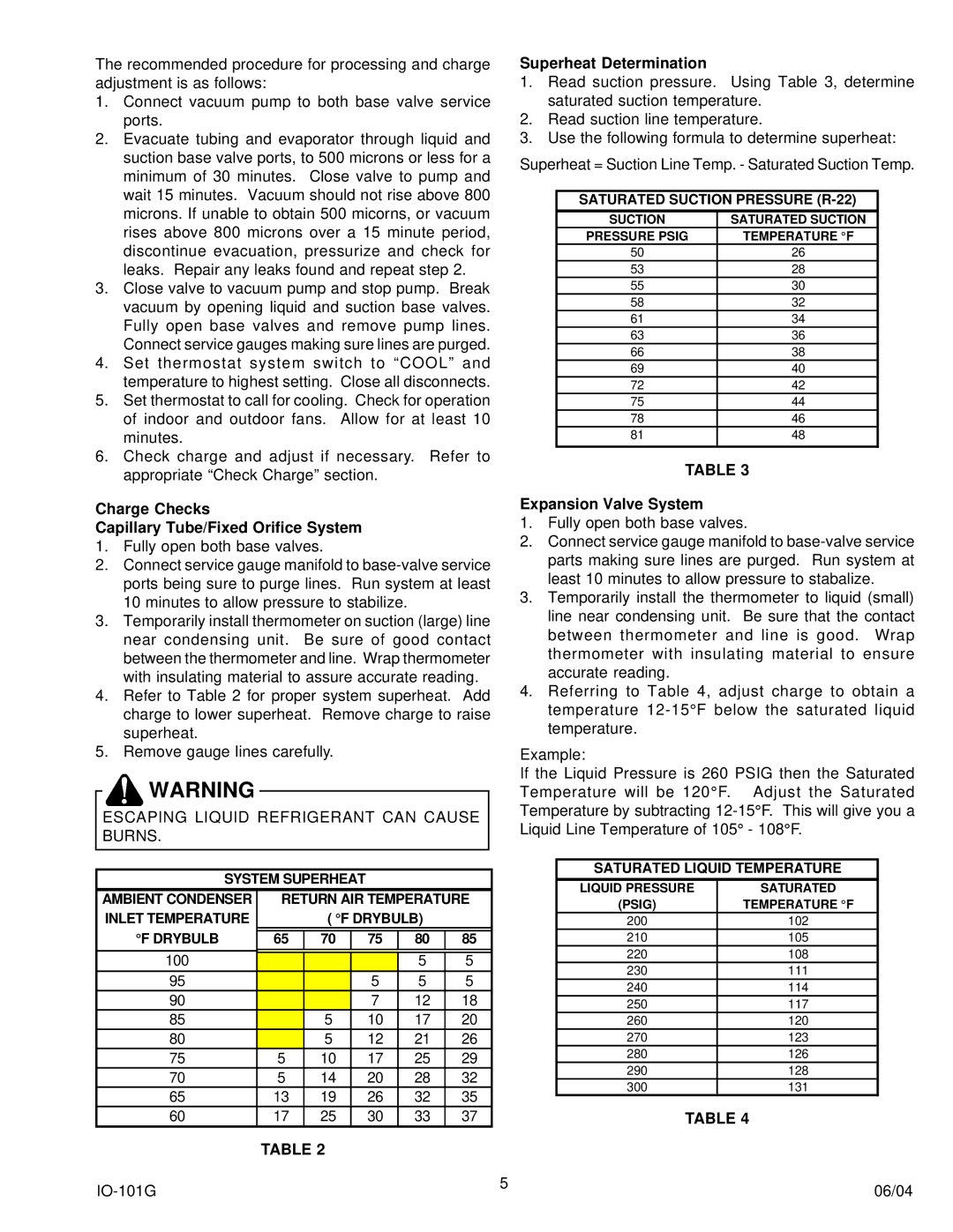
IO-101G specifications
Goodman Manufacturing has long been a trusted name in the heating and cooling industry, and their IO-101G model stands as a robust representation of their commitment to quality and innovation. The IO-101G is a high-efficiency gas furnace designed for residential use, offering an impressive combination of performance, reliability, and comfort.One of the standout features of the IO-101G is its impressive energy efficiency rating. With an Annual Fuel Utilization Efficiency (AFUE) of up to 96%, this furnace ensures that homeowners can enjoy substantial savings on their energy bills while minimizing their environmental footprint. The utilization of advanced heat exchanger technology allows for maximum warmth generation and optimal heat distribution throughout the home.
The IO-101G also incorporates a modulating gas valve and a variable-speed blower motor. This dynamic duo allows the furnace to adjust its heating output to match the demands of the home in real-time, resulting in a more consistent indoor temperature and improved airflow. Homeowners will appreciate the reduced sound levels, as variable-speed motors operate more quietly than their single-speed counterparts.
Another notable characteristic of the IO-101G is its durable construction. Fabricated with high-quality materials and built to withstand the rigors of daily use, this gas furnace promises years of reliable service. Additionally, Goodman includes a comprehensive warranty that speaks to the confidence they have in their product's longevity.
Smart technology integration is also a key aspect of the IO-101G. Many models can be equipped with a Wi-Fi-enabled thermostat, enabling homeowners to easily control their heating system remotely via smartphone or tablet. This modern capability not only enhances convenience but also allows for more precise temperature control, leading to even greater energy efficiency.
The Goodman IO-101G is a perfect example of how modern technology, efficient design, and robust construction can come together to create a top-tier heating solution. With its high AFUE rating, modulating gas valve, durable build, and smart technology options, it's a solid choice for anyone seeking a reliable and efficient gas furnace for their home. As energy costs continue to rise, investing in a high-efficiency furnace like the IO-101G can prove to be a smart decision for today and for the future.

