IMPORTANT: Hard start components are required when
System Startup
PRELIMINARY CHARGE ADJUSTMENT
![]()
![]() CAUTION
CAUTION
If this unit has a crankcase heater (see Specification Sheet or wiring diagram) con- nect electrical power to the unit for four hours before operating the compressor. Failure to do so could result in compressor damage.
IMPORTANT: If adding refrigerant to a system, add only refrigerant vapor (not liquid) through the suction valve (low side) on the outdoor unit. Any other practice may cause compressor damage.
FINAL CHARGE ADJUSTMENT
Matching System
This final charge adjustment procedure is for the matched combination listed on the specification sheet.
If the outdoor temperature is 60°F or higher, set the room thermostat to COOL, fan switch to AUTO, and set the temperature control well below room temperature.
If the outdoor temperature is below 60°F and you are installing a matching system, set the room thermostat to HEAT, fan switch to AUTO, and set the temperature control well above room temperature.
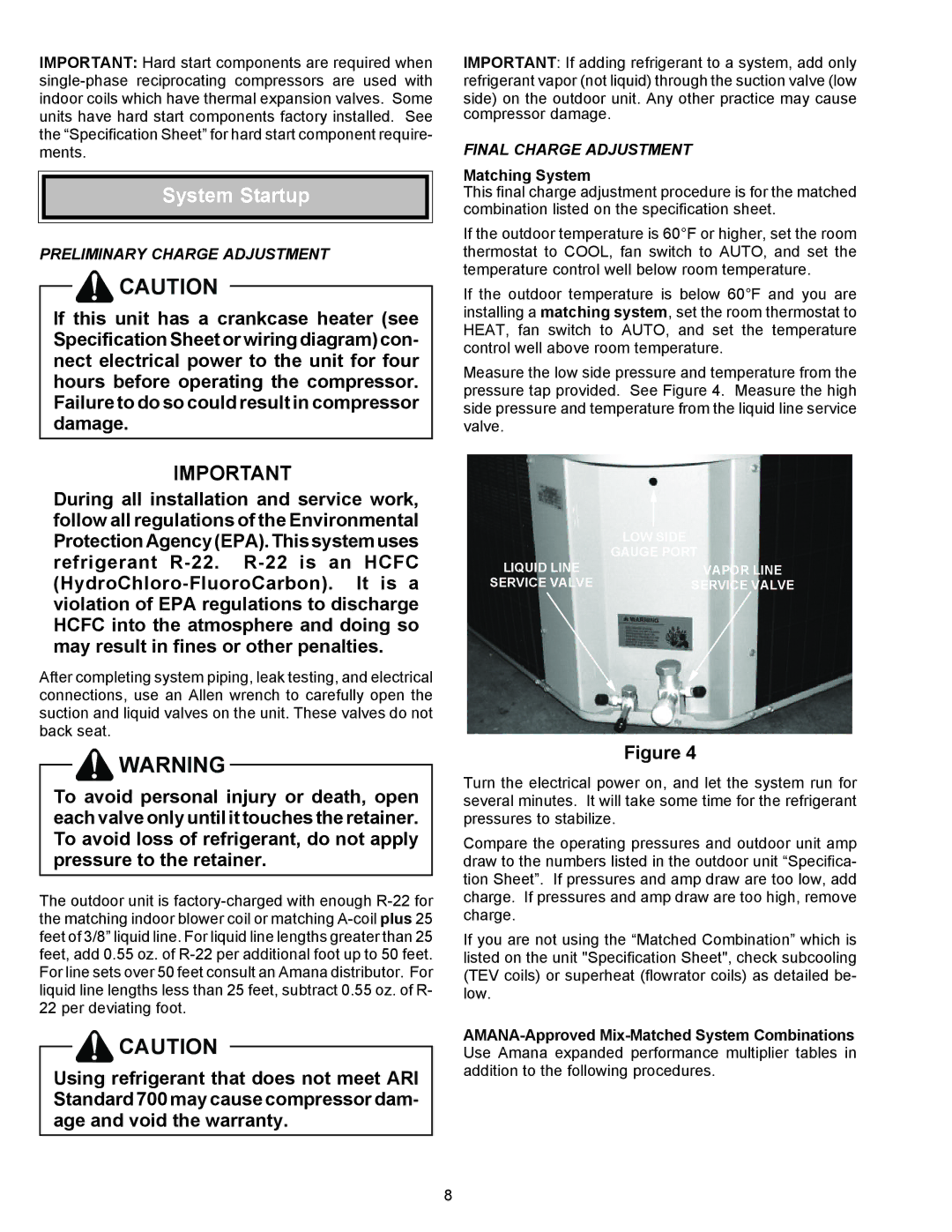
Measure the low side pressure and temperature from the pressure tap provided. See Figure 4. Measure the high side pressure and temperature from the liquid line service valve.
IMPORTANT!
During all installation and service work, follow all regulations of the Environmental Protection Agency (EPA). This system uses refrigerant
After completing system piping, leak testing, and electrical connections, use an Allen wrench to carefully open the suction and liquid valves on the unit. These valves do not back seat.
![]()
![]() WARNING
WARNING
To avoid personal injury or death, open each valve only until it touches the retainer. To avoid loss of refrigerant, do not apply pressure to the retainer.
The outdoor unit is
![]()
![]() CAUTION
CAUTION
Using refrigerant that does not meet ARI Standard 700 may cause compressor dam- age and void the warranty.
| LOW SIDE |
LIQUID LINE | GAUGE PORT |
VAPOR LINE | |
SERVICE VALVE | SERVICE VALVE |
Figure 4
Turn the electrical power on, and let the system run for several minutes. It will take some time for the refrigerant pressures to stabilize.
Compare the operating pressures and outdoor unit amp draw to the numbers listed in the outdoor unit “Specifica- tion Sheet”. If pressures and amp draw are too low, add charge. If pressures and amp draw are too high, remove charge.
If you are not using the “Matched Combination” which is listed on the unit "Specification Sheet", check subcooling (TEV coils) or superheat (flowrator coils) as detailed be- low.
8