Product Specifications

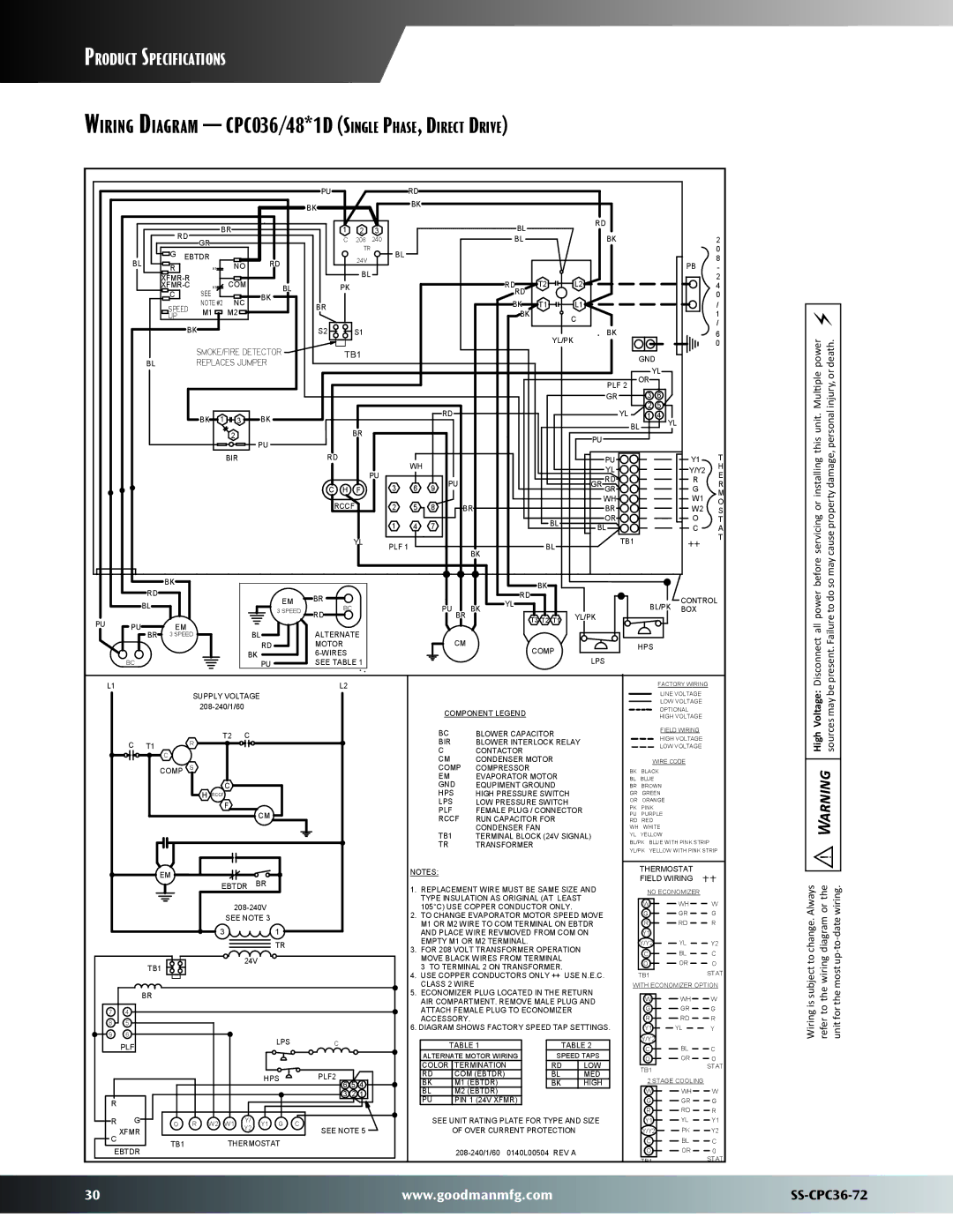
Wiring Diagram CPC036/48*1D (Single Phase, Direct Drive)


PU


RD


BK


BK


BR


1

2

3


BL


RD


RD


GR


C

208

240


BL


BK


2


TR


0


G EBTDR


BL


BL


NO

RD


24V


PB

8


R


K1


BL


-


XFMR-R


COM


RD

T2

L2


2


XFMR-C


K1

BL

PK


4


C

SEE


RD


0


NC

BK


NOTE #2

BR


BK

T1

L1


/


SPEED


M1


M2


BK


1


UP


C


/


BK


S2

S1


BK


6


YL/PK


0


SMOKE/FIRE DETECTOR

TB1


GND


BL


REPLACES JUMPER


YL


PLF 2

OR


GR

3

6


RD


YL

2

5


BK 1

3

BK


1

4


BL

YL


2


BR


PU


PU


BIR


RD


WH


PU


Y1

T


YL


Y/Y2

H


PU


E


PU


GR RD


R


C H

F

3

6

9


R


GR


G

M


WH


W1


RCCF

2

5

8


O


BR


BR


W2

S


1

4

7


BL

OR


O

T


BL


C

A


YL

PLF 1


BL

TB1


++

T


BK


BK


BK


RD


RD


EM

BR


CONTROL


BL


PU BR BK

YL


BL/PK


3 SPEED

BC


BOX


PU

PU

EM


RD


T3 T2 T1

YL/PK


BL

ALTERNATE


BR

3 SPEED


CM


RD

MOTOR


COMP


HPS


BK

6-WIRES


LPS


BC


PU

SEE TABLE 1


power death.

Multiple

injury, or

servicing or installing this unit.

cause property damage, personal

before

so may

Disconnectall power

present. Failure to do

L1

L2


SUPPLY VOLTAGE


208-240/1/60


T2 C

C T1

R


C

COMP S

C

HRCCF

F

CM


EM


BR


EBTDR


208-240V


SEE NOTE 3


3


1


TR


TB1


24V


BR


7

4


8

5


9

6


LPS


PLF


C


HPS

PLF2

5 4


6

R


3 2 1


R

G

O R W2

W1

Y/

Y1 G

C


C XFMR


Y2


SEE NOTE 5

TB1

THERMOSTAT

EBTDR


COMPONENT LEGEND

BC

BLOWER CAPACITOR

BIR

BLOWER INTERLOCK RELAY

C

CONTACTOR

CM

CONDENSER MOTOR

COMP

COMPRESSOR

EM

EVAPORATOR MOTOR

GND

EQUPIMENT GROUND

HPS

HIGH PRESSURE SWITCH

LPS

LOW PRESSURE SWITCH

PLF

FEMALE PLUG / CONNECTOR

RCCF

RUN CAPACITOR FOR

TB1

CONDENSER FAN

TERMINAL BLOCK (24V SIGNAL)

TR

TRANSFORMER

NOTES:

1.REPLACEMENT WIRE MUST BE SAME SIZE AND TYPE INSULATION AS ORIGINAL (AT LEAST 105°C) USE COPPER CONDUCTOR ONLY.

2.TO CHANGE EVAPORATOR MOTOR SPEED MOVE M1 OR M2 WIRE TO COM TERMINAL ON EBTDR AND PLACE WIRE REVMOVED FROM COM ON EMPTY M1 OR M2 TERMINAL.

3.FOR 208 VOLT TRANSFORMER OPERATION MOVE BLACK WIRES FROM TERMINAL

3 TO TERMINAL 2 ON TRANSFORMER.

4.USE COPPER CONDUCTORS ONLY ++ USE N.E.C. CLASS 2 WIRE

5.ECONOMIZER PLUG LOCATED IN THE RETURN AIR COMPARTMENT. REMOVE MALE PLUG AND ATTACH FEMALE PLUG TO ECONOMIZER ACCESSORY.

6.DIAGRAM SHOWS FACTORY SPEED TAP SETTINGS.


TABLE 1


TABLE 2

ALTERNATE MOTOR WIRING


SPEED TAPS

COLOR


TERMINATION


RD

LOW

RD


COM (EBTDR)


BL

MED

BK


M1 (EBTDR)


BK

HIGH

BL


M2 (EBTDR)


PU


PIN 1 (24V XFMR)


SEE UNIT RATING PLATE FOR TYPE AND SIZE

OF OVER CURRENT PROTECTION

208-240/1/60 0140L00504 REV A

FACTORY WIRING

LINE VOLTAGE

LOW VOLTAGE

OPTIONAL

HIGH VOLTAGE

FIELD WIRING

HIGH VOLTAGE

LOW VOLTAGE

WIRE CODE

BK BLACK

BL BLUE BR BROWN GR GREEN OR ORANGE

PK PINK PU PURPLE RD RED WH WHITE

YL YELLOW

BL/PK BLUE WITH PINK STRIP YL/PK YELLOW WITH PINK STRIP

THERMOSTAT

FIELD WIRING

NO ECONOMIZER


W

WH

W

G

GR

G

R

RD

R

Y1


Y/Y2

YL

Y2

C

BL

C

O

OR

O

TB1


STAT

WITH ECONOMIZER OPTION

W

WH

W

G

GR

G

R

RD

R

Y1

YL

Y

Y/Y2


C

BL

C

O

OR

O

TB1


STAT


2 STAGE COOLING


W

WH

W

G

GR

G

R

RD

R

Y1

YL

Y1

Y/Y2

PK

Y2

C

BL

C

O

OR

O

TB1


STAT


High Voltage: sources may be


Warning

Always or the wiring.

change. diagram -to-date

Wiring is subject to refer to the wiring unit for the most up

30

www.goodmanmfg.com

SS-CPC36-72

Page 30
Image 30
Goodman Mfg SS-CPC36-72 dimensions Wiring Diagram CPC036/48*1D Single Phase, Direct Drive

SS-CPC36-72 specifications

The Goodman Manufacturing SS-CPC36-72 is a top-tier commercial rooftop unit designed for optimal heating and cooling in a variety of settings. This unit embodies the cutting-edge technology and engineering expertise that Goodman is known for. Ideal for medium to large commercial buildings, the SS-CPC36-72 stands out with its robust performance and energy efficiency.

One of the defining features of this unit is its high-efficiency scroll compressor, which significantly enhances energy savings while providing reliable performance. The compressor operates quietly and has fewer moving parts compared to traditional compressors, resulting in lower maintenance requirements. This feature is critical for environments where noise levels must be minimized.

Additionally, the Goodman SS-CPC36-72 is designed with a multi-stage cooling system. This technology allows the unit to operate at varying capacities, adapting to real-time cooling needs. This not only improves comfort levels in the space but also optimizes energy use, leading to reduced operational costs.

Another notable characteristic of this model is its environmentally friendly R-410A refrigerant. The use of this refrigerant contributes to lower global warming potential, aligning with modern sustainability goals. This makes the Goodman SS-CPC36-72 not just a powerful unit but also an environmentally conscious choice for businesses looking to reduce their carbon footprint.

The unit is built with durable materials, ensuring longevity and resilience in various weather conditions. From the corrosion-resistant cabinet to the high-quality insulation, every component is crafted to withstand the rigors of commercial environments. This durability translates to reduced replacement costs over time, making it a wise investment.

Ease of installation and maintenance is another hallmark of the Goodman SS-CPC36-72. The unit is designed with serviceability in mind, featuring accessible components that simplify routine checks and repairs. This means reduced downtime and enhanced productivity for businesses relying on consistent climate control.

In summary, the Goodman Mfg SS-CPC36-72 is a highly efficient and versatile rooftop HVAC unit. With its advanced compressor technology, environmentally friendly refrigerant, robust construction, and easy maintenance features, it is well-equipped to meet the demands of modern commercial spaces while delivering exceptional performance and reliability.