Air Motor Service
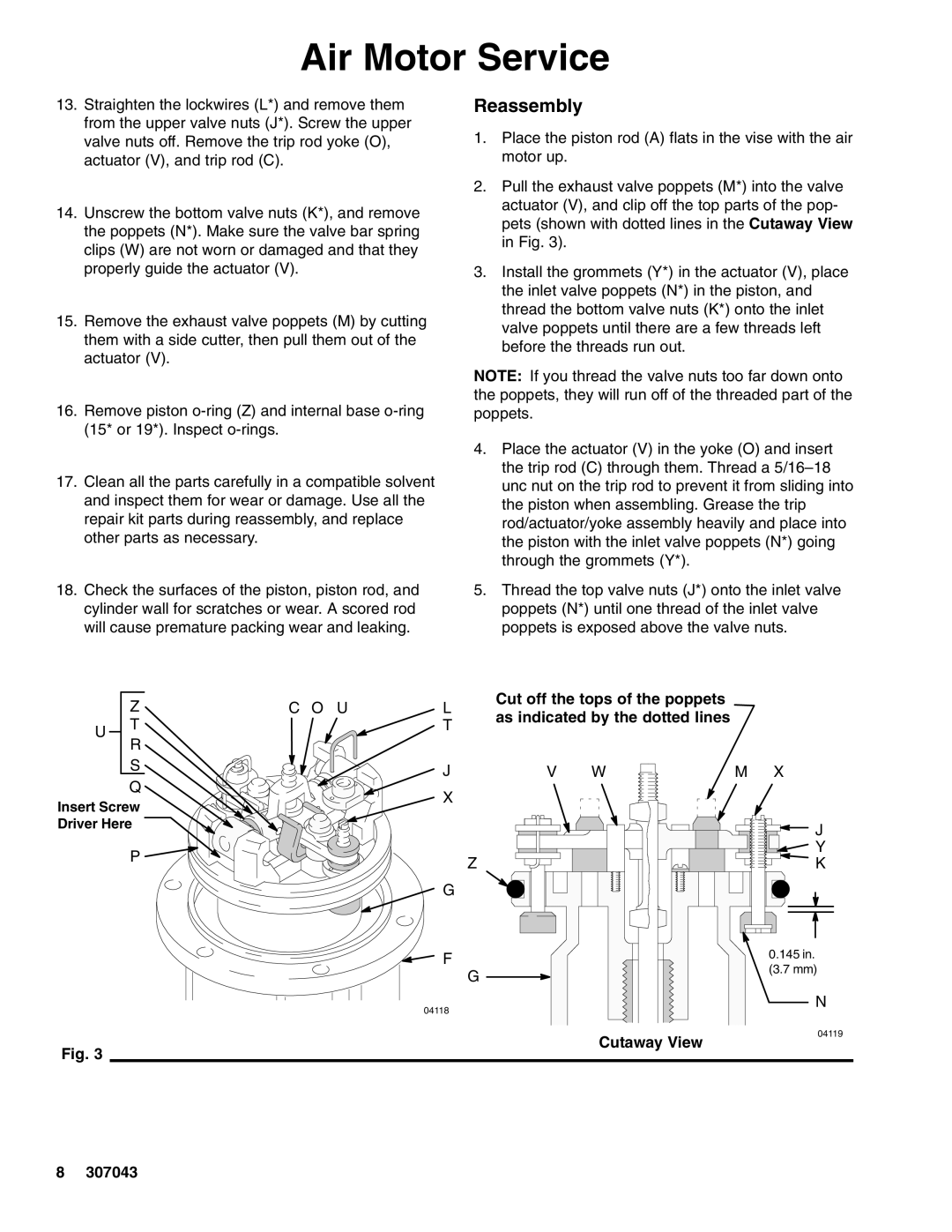
13.Straighten the lockwires (L*) and remove them from the upper valve nuts (J*). Screw the upper valve nuts off. Remove the trip rod yoke (O), actuator (V), and trip rod (C).
14.Unscrew the bottom valve nuts (K*), and remove the poppets (N*). Make sure the valve bar spring clips (W) are not worn or damaged and that they properly guide the actuator (V).
15.Remove the exhaust valve poppets (M) by cutting them with a side cutter, then pull them out of the actuator (V).
16.Remove piston
17.Clean all the parts carefully in a compatible solvent and inspect them for wear or damage. Use all the repair kit parts during reassembly, and replace other parts as necessary.
Reassembly
1.Place the piston rod (A) flats in the vise with the air motor up.
2.Pull the exhaust valve poppets (M*) into the valve actuator (V), and clip off the top parts of the pop- pets (shown with dotted lines in the Cutaway View in Fig. 3).
3.Install the grommets (Y*) in the actuator (V), place the inlet valve poppets (N*) in the piston, and thread the bottom valve nuts (K*) onto the inlet valve poppets until there are a few threads left before the threads run out.
NOTE: If you thread the valve nuts too far down onto the poppets, they will run off of the threaded part of the poppets.
4.Place the actuator (V) in the yoke (O) and insert the trip rod (C) through them. Thread a
18.Check the surfaces of the piston, piston rod, and cylinder wall for scratches or wear. A scored rod will cause premature packing wear and leaking.
5.Thread the top valve nuts (J*) onto the inlet valve poppets (N*) until one thread of the inlet valve poppets is exposed above the valve nuts.
Z
UT R
S
Q
Insert Screw
Driver Here
P ![]()
C O U | L | Cut off the tops of the poppets |
| |
as indicated by the dotted lines |
| |||
| T |
| ||
|
|
|
| |
| J | V | W | M X |
| X |
|
|
|
|
|
|
| J |
|
|
|
| Y |
| Z |
|
| K |
| G |
|
|
|
| F |
|
| 0.145 in. |
| G |
|
| (3.7 mm) |
|
|
|
| |
N
Fig. 3
04118
Cutaway View
04119
8 307043
