'2. Remove oiler from air motor topcap. See
,Pig. . 5. Fill oiler with kerosene. Replace oiler.
>.
3.dllow a soaking period of,5 to 10 minutes, then starta b motor. Run motor slowly. After smooth operationhas been achieved and kerosene has been blown from a*haUSt. stop LUOtOr, remove ouer screw and fFu oiler with a lightair motor oil.
NOTE: MAgE NO ATPMPT M DISASSMBLB ADl MUl'a. If it should needrepab, contact pour nearest Graco Authorized %mice Depot.
FLUID SHUTOFF VALVE
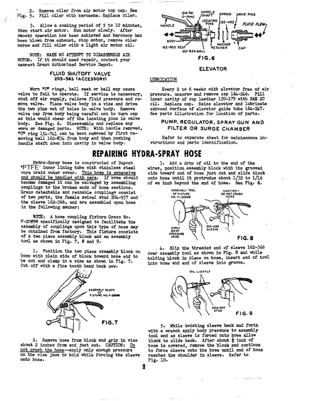
Worn "0" rings, ball seat or ball may cause valve to failto operate. If sesvice is necessary, shut offair supply, relieve fluid pressure and re- move valve. Place valvebody in a vise and drive the two pina outof holes in valve body. Runwe valve cap from body being careful not to turn cap as this would shearoff the locating pins in valve body. See Fig. 6. Disassemble andreplace any worn or damaged parts. NOTE: W i t h handle removed, "On ring
. .
f I G . 6
ELEVATOR
LUERICATION
Every 2 to 6 weeks with elevator freeof air pressure, unscrew and remove cap
PUMP. REGULATOR, SPRAY GUN AND FILTER OR SURGE CHAMBER
Refer to separate sheetfor maintenance in- structions and parts identification.
REPAIRING HYDRA-SPRAY HOSE
hoseis constructed | oftiupont |
| 3. Add | a | dropof oil to the | endof | the | |||||||||
"PTFE | inner lining tube with | stainlesssteal | vires, position assembly.block vithstI groovad | |||||||||||||
wire braid Outer | CWer. | This hose is exoensive | side | towardend | of | hosejust | cut | andslide block | ||||||||
and shouldbe handled withcare. | If hose should | onto | hoseuntil | it | protrudes | about1/32 | to 1/16 | |||||||||
becane | damagedit can be | salvaged by | assembling | of | an | inch | beyond | the endof | hose. | See | Fig. 8. | |||||
Couplings to | the | broken | ends | of | hose | sections. |
|
| ASSEMW | moL | CIUIION - |
| ||||
Graco detachable | and reusable couplings consist |
|
| or rmrunc |
| DO NOT CRUSH |
| |||||||||
Of two parts. | the female M v e l stud |
|
| no. |
| HO5L |
| |||||||||
the sleeve | are | assembledupon hose | . . | ~ |
|
|
|
|
|
|
| |||||
in the | followingmanner: |
|
|
|
|
|
|
|
|
|
|
|
|
| ||
NUTE: A hose coupling fixture Graco No.
.
4. a p the threadede.nd of sleeve
be cut and clamp in a d s e as shown in Fig. 7. into hose and end ofsleeve intogroove.
Cut off With a finetooth hand hack saw.
2.Remove hose from block and grip In vise about 2 inches from end just cut. CAUTION: 00 not crush the
5.While twisting sleeve back and forth vith awrench apply body pressure to assembly t d and as sleeve is forced onto hoseallow block to slide back. After about & inch Of hose is covered, remove the block and continue to force sleeve ontothe hose until end ofhose reaches the shoulder in sleeve. Refer to
Fig. 10.
9