Installation
Typical Installation
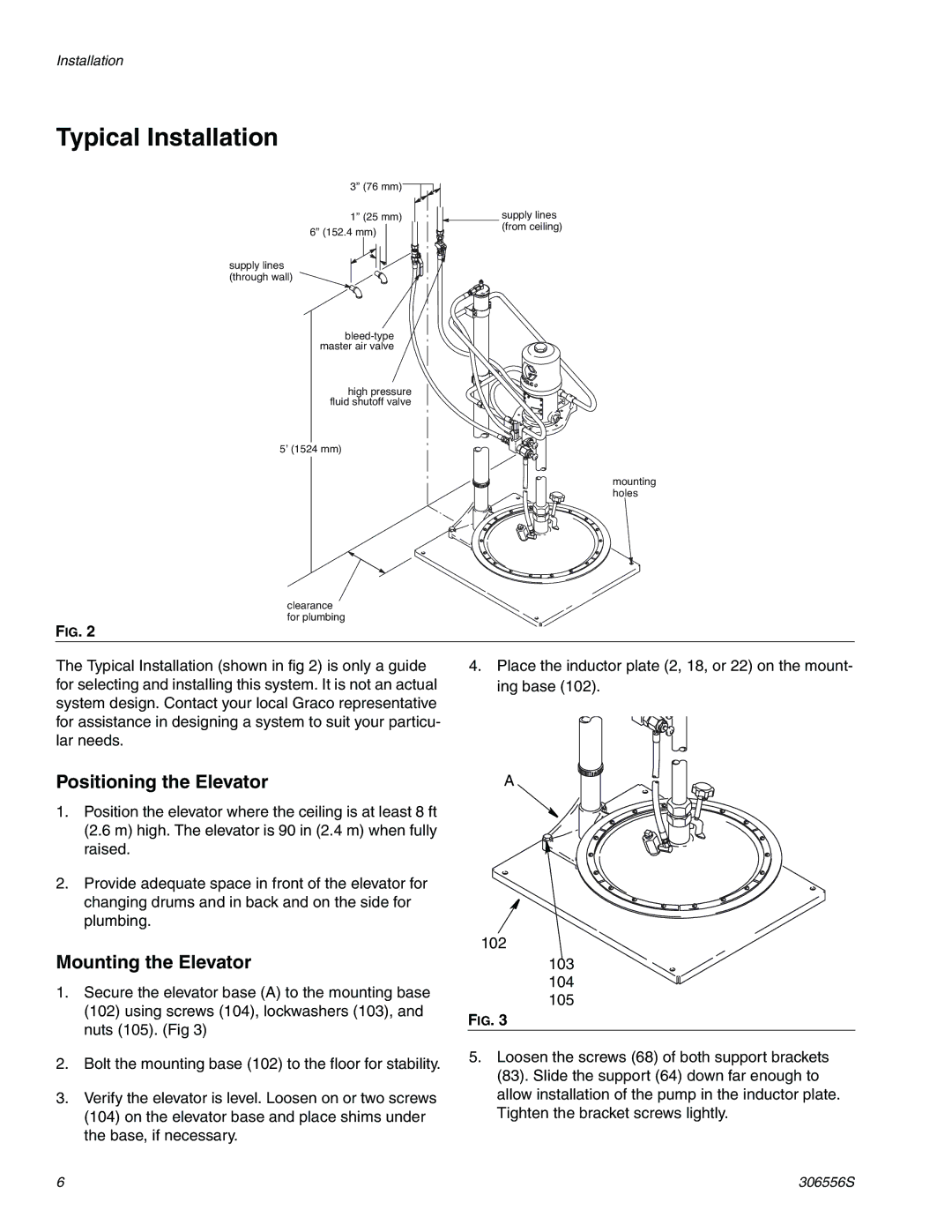
3” (76 mm)![]()
![]()
1” (25 mm)
6” (152.4 mm)
supply lines (through wall)
high pressure fluid shutoff valve
5’ (1524 mm)
clearance for plumbing
FIG. 2
supply lines (from ceiling)
mounting holes
The Typical Installation (shown in fig 2) is only a guide for selecting and installing this system. It is not an actual system design. Contact your local Graco representative for assistance in designing a system to suit your particu- lar needs.
4.Place the inductor plate (2, 18, or 22) on the mount- ing base (102).
Positioning the Elevator
1.Position the elevator where the ceiling is at least 8 ft (2.6 m) high. The elevator is 90 in (2.4 m) when fully raised.
2.Provide adequate space in front of the elevator for changing drums and in back and on the side for plumbing.
Mounting the Elevator
1.Secure the elevator base (A) to the mounting base
(102)using screws (104), lockwashers (103), and nuts (105). (Fig 3)
2.Bolt the mounting base (102) to the floor for stability.
3.Verify the elevator is level. Loosen on or two screws
(104)on the elevator base and place shims under the base, if necessary.
A
102
103
104
105
FIG. 3
5.Loosen the screws (68) of both support brackets (83). Slide the support (64) down far enough to allow installation of the pump in the inductor plate. Tighten the bracket screws lightly.
6 | 306556S |