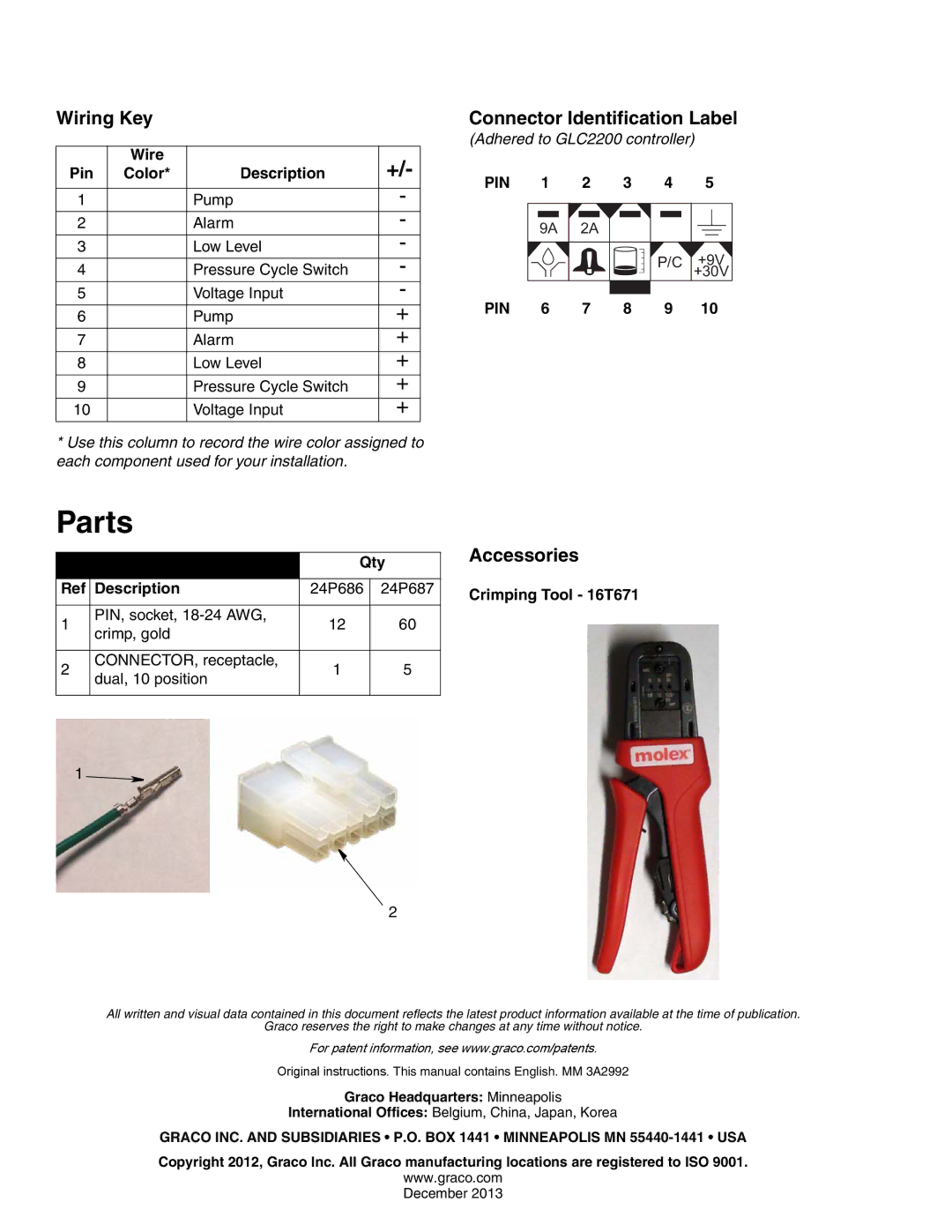
Wiring Key
| Wire |
| +/- |
Pin | Color* | Description | |
|
|
|
|
1 |
| Pump | - |
2 |
| Alarm | - |
3 |
| Low Level | - |
4 |
| Pressure Cycle Switch | - |
5 |
| Voltage Input | - |
6 |
| Pump | + |
7 |
| Alarm | + |
8 |
| Low Level | + |
9 |
| Pressure Cycle Switch | + |
10 |
| Voltage Input | + |
Connector Identification Label
(Adhered to GLC2200 controller)
PIN | 1 | 2 | 3 | 4 | 5 |
| 9A | 2A |
|
|
|
|
|
|
| P/C | +9V |
|
|
|
|
| +30V |
PIN | 6 | 7 | 8 | 9 | 10 |
*Use this column to record the wire color assigned to each component used for your installation.
Parts
|
| Qty | ||
|
|
|
| |
Ref | Description | 24P686 | 24P687 | |
|
|
|
| |
1 | PIN, socket, | 12 | 60 | |
crimp, gold | ||||
|
|
| ||
|
|
|
| |
2 | CONNECTOR, receptacle, | 1 | 5 | |
dual, 10 position | ||||
|
|
| ||
|
|
|
| |
1 ![]()
2
Accessories
Crimping Tool - 16T671
All written and visual data contained in this document reflects the latest product information available at the time of publication.
Graco reserves the right to make changes at any time without notice.
For patent information, see www.graco.com/patents.
Original instructions. This manual contains English. MM 3A2992
Graco Headquarters: Minneapolis
International Offices: Belgium, China, Japan, Korea
GRACO INC. AND SUBSIDIARIES • P.O. BOX 1441 • MINNEAPOLIS MN
Copyright 2012, Graco Inc. All Graco manufacturing locations are registered to ISO 9001.
www.graco.com
December 2013
