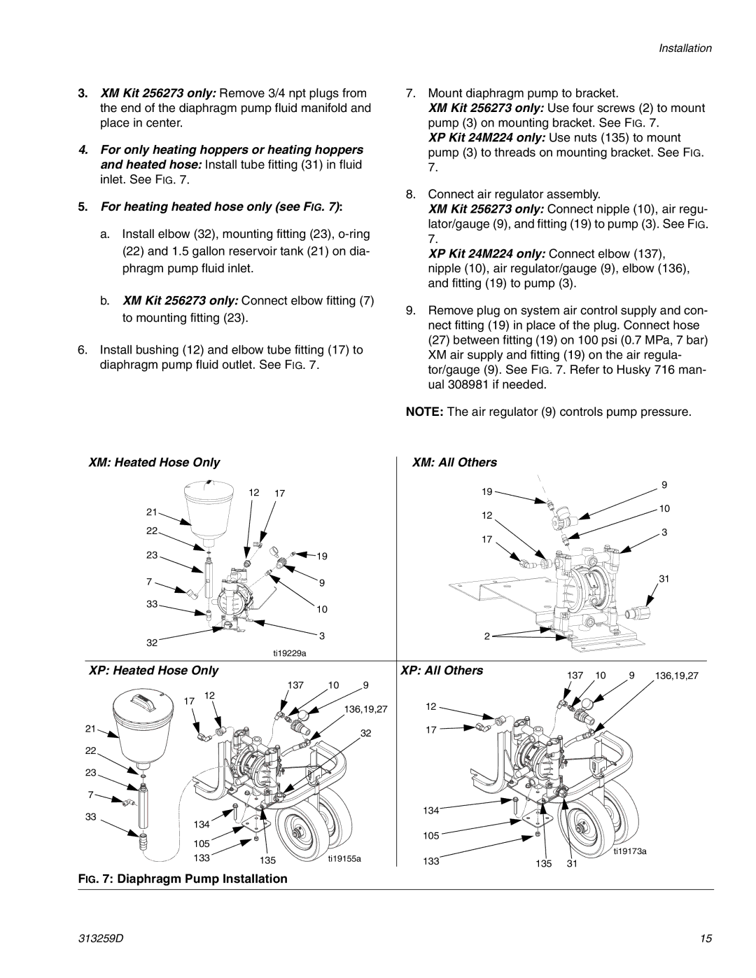
3.XM Kit 256273 only: Remove 3/4 npt plugs from the end of the diaphragm pump fluid manifold and place in center.
4.For only heating hoppers or heating hoppers and heated hose: Install tube fitting (31) in fluid inlet. See FIG. 7.
5.For heating heated hose only (see FIG. 7):
a.Install elbow (32), mounting fitting (23),
b.XM Kit 256273 only: Connect elbow fitting (7) to mounting fitting (23).
6.Install bushing (12) and elbow tube fitting (17) to diaphragm pump fluid outlet. See FIG. 7.
Installation
7.Mount diaphragm pump to bracket.
XM Kit 256273 only: Use four screws (2) to mount pump (3) on mounting bracket. See FIG. 7.
XP Kit 24M224 only: Use nuts (135) to mount pump (3) to threads on mounting bracket. See FIG. 7.
8.Connect air regulator assembly.
XM Kit 256273 only: Connect nipple (10), air regu- lator/gauge (9), and fitting (19) to pump (3). See FIG. 7.
XP Kit 24M224 only: Connect elbow (137), nipple (10), air regulator/gauge (9), elbow (136), and fitting (19) to pump (3).
9.Remove plug on system air control supply and con- nect fitting (19) in place of the plug. Connect hose (27) between fitting (19) on 100 psi (0.7 MPa, 7 bar) XM air supply and fitting (19) on the air regula- tor/gauge (9). See FIG. 7. Refer to Husky 716 man- ual 308981 if needed.
NOTE: The air regulator (9) controls pump pressure.
XM: Heated Hose Only |
|
|
| XM: All Others |
|
|
|
|
| |
| 12 | 17 |
|
| 19 |
|
|
|
| 9 |
|
|
|
|
|
|
|
| |||
21 |
|
|
|
| 12 |
|
|
|
| 10 |
|
|
|
|
|
|
|
|
| ||
|
|
|
|
|
|
|
|
|
| |
22 |
|
|
|
| 17 |
|
|
|
| 3 |
|
|
|
|
|
|
|
|
|
| |
23 |
|
| 19 |
|
|
|
|
|
|
|
7 |
|
| 9 |
|
|
|
|
|
| 31 |
|
|
|
|
|
|
|
|
| ||
33 |
|
| 10 |
|
|
|
|
|
|
|
|
|
|
|
|
|
|
|
|
| |
32 |
|
| 3 |
| 2 |
|
|
|
|
|
|
|
|
|
|
|
|
|
|
| |
|
| ti19229a |
|
|
|
|
|
|
|
|
XP: Heated Hose Only |
|
|
| XP: All Others |
| 137 | 10 | 9 | 136,19,27 | |
|
| 137 | 10 | 9 |
|
| ||||
| 12 |
|
|
|
|
|
| |||
17 |
|
| 136,19,27 | 12 |
|
|
|
|
| |
|
|
|
|
|
|
|
|
| ||
21 |
|
|
| 32 | 17 |
|
|
|
|
|
|
|
|
|
|
|
|
|
|
| |
22 |
|
|
|
|
|
|
|
|
|
|
23 |
|
|
|
|
|
|
|
|
|
|
7 |
|
|
|
|
|
|
|
|
|
|
33 |
|
|
|
| 134 |
|
|
|
|
|
|
|
|
|
|
|
|
|
|
| |
134 |
|
|
|
|
|
|
|
|
| |
105 |
|
|
| 105 |
|
|
|
|
| |
|
|
|
|
|
|
| ti19173a |
| ||
133 | 135 | ti19155a | 133 |
|
|
|
| |||
135 | 31 |
|
|
| ||||||
FIG. 7: Diaphragm Pump Installation
313259D | 15 |
