Typical Installation
Typical Installation
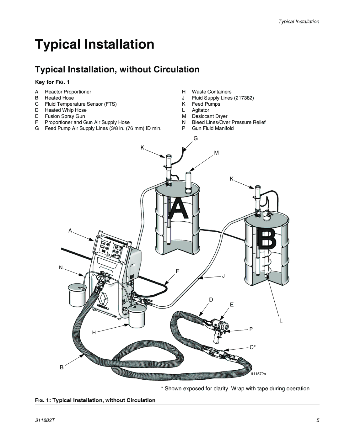
Typical Installation, without Circulation
Key for FIG. 1
A | Reactor Proportioner | H | Waste Containers |
B | Heated Hose | J | Fluid Supply Lines (217382) |
C | Fluid Temperature Sensor (FTS) | K | Feed Pumps |
D | Heated Whip Hose | L | Agitator |
E | Fusion Spray Gun | M | Desiccant Dryer |
F | Proportioner and Gun Air Supply Hose | N | Bleed Lines/Over Pressure Relief |
G | Feed Pump Air Supply Lines (3/8 in. (76 mm) ID min. | P | Gun Fluid Manifold |
|
|
| G |
| K |
| M |
|
|
| |
|
|
| K |
A
N
F
![]() J
J
D
E
H
L
P
![]() C*
C*
B
ti11572a
* Shown exposed for clarity. Wrap with tape during operation.
FIG. 1: Typical Installation, without Circulation
311882T | 5 |
