Repair
7.Lubricate and install the new
NOTICE
The orientation of the ball valves in the inlet and outlet valve housings is critical. Install the parts of the ball valve exactly as instructed and refer to FIG. 5. If installed incorrectly, the pump will not operate.
8.Place the inlet valve housing (7) on a flat surface with the ball valve openings facing up. Lubricate the seals (17*) and set them into each side of the inlet valve housing.
9.Place the ball guides (16) and balls (18) in the inlet valve housing.
11.Apply removable (blue) Loctite® 243 to entire length of the screw (9) threads. Position the inlet manifold
(1) on the inlet valve housing (1). Install the twelve capscrews (9) and lockwashers (8) loosely.
12.Tighten the four inside screws (9) oppositely and evenly to 3 N•m (27
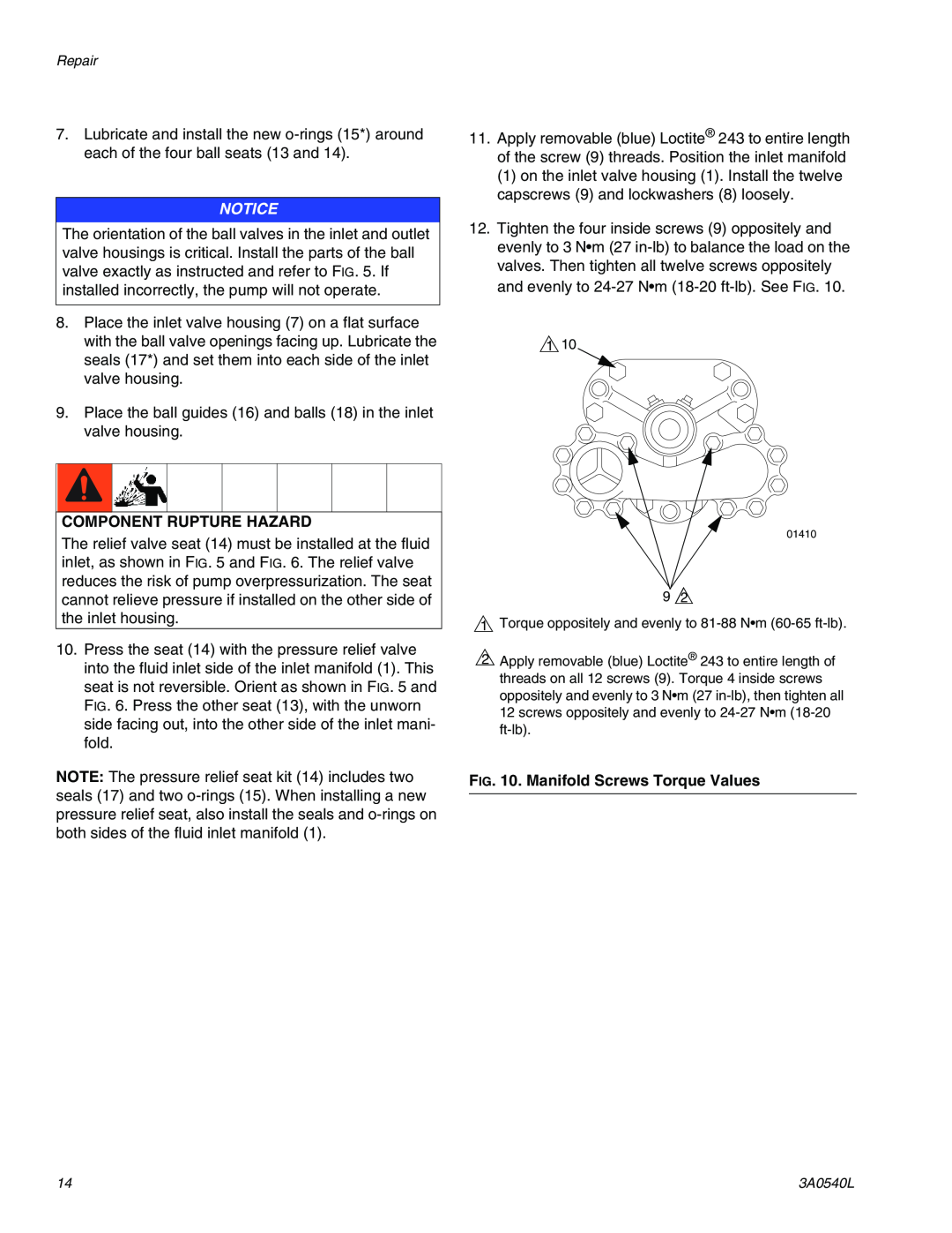
1 10
COMPONENT RUPTURE HAZARD
The relief valve seat (14) must be installed at the fluid inlet, as shown in FIG. 5 and FIG. 6. The relief valve reduces the risk of pump overpressurization. The seat cannot relieve pressure if installed on the other side of the inlet housing.
10.Press the seat (14) with the pressure relief valve into the fluid inlet side of the inlet manifold (1). This seat is not reversible. Orient as shown in FIG. 5 and FIG. 6. Press the other seat (13), with the unworn side facing out, into the other side of the inlet mani- fold.
NOTE: The pressure relief seat kit (14) includes two seals (17) and two
01410
9 2
1 Torque oppositely and evenly to
2Apply removable (blue) Loctite® 243 to entire length of threads on all 12 screws (9). Torque 4 inside screws oppositely and evenly to 3 N•m (27
FIG. 10. Manifold Screws Torque Values
14 | 3A0540L |