Setup
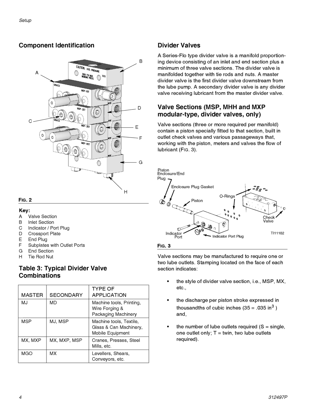
Component Identification
B
A
D
C ![]()
E
![]() F
F
G
H
FIG. 2
Key:
AValve Section
BInlet Section
CIndicator / Port Plug
DCrossport Plate
EEnd Plug
FSubplates with Outlet Ports
GEnd Section
HTie Rod Nut
Table 3: Typical Divider Valve
Combinations
|
| TYPE OF |
MASTER | SECONDARY | APPLICATION |
MJ | MD | Machine tools, Printing, |
|
| Wire Forging & |
|
| Packaging Machinery |
MSP | MJ, MSP | Machine tools, Textile, |
|
| Glass & Can Machinery, |
|
| Mobile Equipment |
MX, MXP | MX, MXP, MSP | Cranes, Presses, Steel |
|
| Mills, etc. |
|
|
|
MGO | MX | Levellers, Shears, |
|
| Conveyors, etc. |
Divider Valves
A
Valve Sections (MSP, MHH and MXP
Valve sections (three or more required per manifold) contain a piston specially fitted to that section, built in outlet check valves and various passageways that, working with the piston, meters and valves the flow of lubricant (FIG. 3).
Piston
Enclosure/End
Plug
Enclosure Plug Gasket
Piston
Check
Valve
Indicator | TI11102 |
Port | Indicator Port Plug |
FIG. 3
Valve sections may be manufactured to require one or two lube outlets. Stamping located on the face of each section indicates:
•the style of divider valve section, i.e., MSP, MX, etc.,
•the discharge per piston stroke expressed in thousandths of cubic inches (35 = .035 in3 ) and,
•the number of lube outlets required (S = single, one outlet only; T = twin, two lube outlets required).
4 | 312497P |